Method, apparatus, system and computer program product for identifying failing or failed optical network terminal(s) on an optical distribution network

a technology of optical network terminals and optical distribution networks, applied in transmission monitoring, transmission monitoring/testing/fault-measurement systems, electrical devices, etc., can solve problems such as and inability to detect failures. to achieve the effect of less costly, time-consuming, and less costly correction

Inactive Publication Date: 2007-08-30
TELLABS PETALUMA
View PDF10 Cites 65 Cited by
  • Summary
  • Abstract
  • Description
  • Claims
  • Application Information

AI Technical Summary

Benefits of technology

[0019] An advantage of the present invention is that malfunctioning ONTs or other problems, such as damaged fibers, can be detected without disconnecting the PON components. Another advantage of the present invention is that it identifies the above-mentioned malfunctions in a more timely and less costly manner than do conventional troubleshooting techniques. The present invention also identifies the cause of the aforementioned faults and provides more information to avoid faults and categorize problems.
[0020] Advantageously, the present invention detects ONT malfunctions earlier than conventional techniques, leading to a more timely and less costly correction of the aforementioned problems, and reduced customer down time.
[0021] With the present invention, no additional test equipment is required as the OLT either has, or could easily be built to have, all of the needed capability for detecting problems, and identifying the exact ONT with a problem, once it is programmed according to the invention to do so.
[0022] In accordance with one embodiment of the present invention, there is provided a method, apparatus, system and computer program product for identifying an error in a passive optical network including communicating to an optical network terminal on the passive optical network a request to transmit a response signal at a predetermined power level and receiving the response signal in response to the request. This embodiment also provides measuring a power level of the response signal and comparing a predetermined channel power level to the power level of the response signal. A status of the optical network terminal is determined based on a result of the comparing.
[0023] In accordance with another embodiment of the present invention, there is provided a method, apparatus, system and computer program product for identifying an error in a passive optical network including measuring a power level of a signal on the passive optical network, comparing the measured power level to at least one predetermined power level, and determining a fault based on the comparing.
[0024] Further features and advantages of the present invention as well as the structure and operation of various embodiments of the present invention are described in detail below with reference to the accompanying drawings.

Problems solved by technology

Upstream traffic is more complicated due to the shared media nature of the ODN.
As with most electronic equipment, an ONT can malfunction.
In some cases ONT malfunctions are catastrophic to communications.
This can make it impossible for the OLT to communicate with any of the ONTs on the ODN.
In addition, once an ONT is ranged, the presence of an error might be undetectable until ranging reoccurs.
Thus, only when the ranging process needs to reoccur will such a range blocking type error be detected.
This results in the OLT not being able to communicate with any of the ONTs on the ODN.
A malfunctioning ONT might also send a signal up to the OLT with an inappropriate power level.
This can occur, for instance, when an ONT laser begins to fail.
This problem can also occur, for example, due to a failing laser.
In either case, the problem can make it impossible for the OLT to communicate with that ONT on a continuous basis and can cause disruptions in service, and signal sporadic alarms from either the OLT or ONT to a network operator as communications are lost.
Using existing error detection techniques (e.g., those described in the various PON protocols), the above-identified ONT malfunctions may not be detected or, even if detected (e.g., by system failure), may not be identified.
Nor do these conventional troubleshooting techniques identify in situ the identity of the problem ONT.
Moreover, it becomes impractical and relatively expensive to remove ONTs one by one to repair them.
Yet, in some cases the presence of a modulated or un-modulated signal can be used to indicate a system problem even though it may not actually result from communication problems between an OLT and an ONT.
In addition, the ends of the fiber optic medium can get dirty or the fiber can inadvertently become bent, which can undesirably attenuate different wavelengths of the transmitted light causing additional problems.
These types of malfunctions typically go undetected or are detected only after a total communications failure.

Method used


Image

  • Method, apparatus, system and computer program product for identifying failing or failed optical network terminal(s) on an optical distribution network
  • Method, apparatus, system and computer program product for identifying failing or failed optical network terminal(s) on an optical distribution network
  • Method, apparatus, system and computer program product for identifying failing or failed optical network terminal(s) on an optical distribution network

Examples


Embodiment Construction

[0029] The present invention is now described in more detail herein in terms of an exemplary system, apparatus, method and computer program product for identifying a malfunctioning ONT in a PON ODN. This system is described for illustration purposes and is not intended to limit the application and scope of the present invention. In fact, after reading the following description, it will be apparent to one skilled in the relevant art(s) how to implement the following invention in alternative embodiments (e.g., B-PON, EPON, APON, etc.).

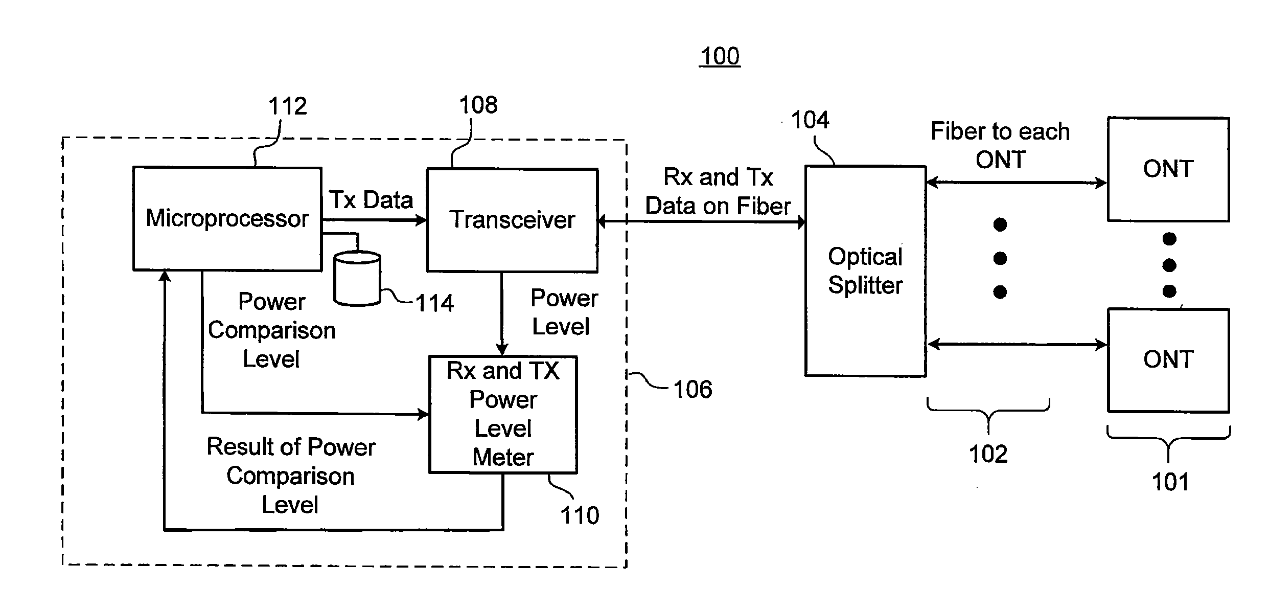
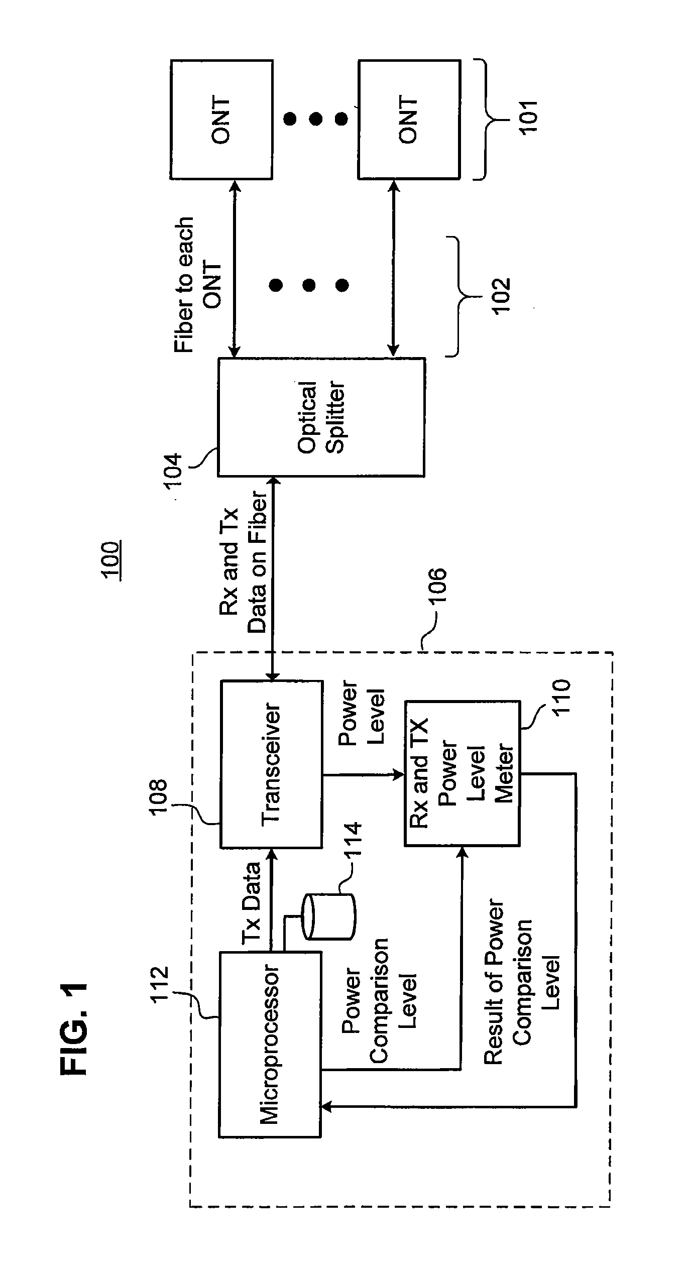
[0030]FIG. 1 is a system diagram of an exemplary PON 100 in which the present invention, according to one embodiment, can be implemented. System 100 includes an OLT 106 which is communicatively coupled to an optical splitter 104 through an interface that can include, for example, fiber optic cabling and / or an other suitable type of interface. Optical splitter 104, in turn, distributes optical signals through an interface, such as optical fibers 102 and / ...


PUM


Abstract

An error in a passive optical network is identified by communicating to an optical network terminal on the passive optical network a request to transmit a response signal at a predetermined power level, receiving the response signal in response to the request, and measuring a power level of the response signal. A predetermined channel power level is compared to the power level of the response signal and a status of the optical network terminal is determined based on the result of the comparison.

Description

CROSS REFERENCE TO RELATED APPLICATIONS [0001] This application claims priority to, and the benefit of, U.S. Provisional Patent Application Ser. No. 60 / 743,380, filed Feb. 28, 2006, which is hereby incorporated by reference in its entirety.BACKGROUND OF THE INVENTION [0002] 1. Field Of The Invention [0003] The present invention generally relates to passive optical networking (PON) error detection, and more particularly to identifying optical network terminal (ONT) malfunctions within a PON. [0004] 2. Related Art [0005] Generally, a passive optical network (PON) is made up of fiber optic cabling, passive splitters and couplers that distribute an optical signal through a branched tree topology referred to as an optical distribution network (ODN). Each fiber segment is terminated at a connector to make a connection to devices at a customer's premises. A PON optical-line terminal (OLT) transmits a light signal through the fiber and passive splitters, and distributes the light signal to ...

Claims


Application Information

Patent Timeline
Patent Type & Authority Applications(United States)
IPC IPC(8): H04B10/08
CPCH04B10/07955H04B10/077
Inventor DELEW, DAVID A.MIGUEL, JOSEPH D.EGBERTS, BERNARDUS F.
Owner TELLABS PETALUMA
Why Eureka
Try Eureka