
Liquid applicator

Active Publication Date: 2007-08-30
U MARK
View PDF8 Cites 18 Cited by
  • Summary
  • Abstract
  • Description
  • Claims
  • Application Information

AI Technical Summary

Benefits of technology

[0008] This liquid applicator requires only four components, in addition to the nib, to work effectively. These four components are a closure, a plunger or valve element, a spring and a retainer. When assembled in proper order in a container, which provides the applicator body, the applicator works effectively as a valve to regulate flow from the container to the nib. In addition to the four components and the nib, only a cap is necessary, as an addition, to prevent the applicator from drying out when not in use.
[0013] It is yet another aspect of this invention to provide that the first part of the closure passage provides a reservoir for the liquid and also provides a plurality of longitudinal ribs facilitating movement of the nib within said passage.
[0017] It is an aspect of this invention to provide a cap adapted to overfit the closure and slidingly engage with the closure to maintain alignment of the cap and inhibit drying out of the nib.
[0018] This liquid applicator is simple in construction because of the reduction in component parts, and it is easy to manufacture and use for the same reason.
[0019] It is an aspect of this invention to provide a proper fit of the aluminum container and the closure to prevent liquid leaks. Leakage may be due to the extremes of temperature in which the applicator is used and particularly because aluminum of the container and the plastic of the closure have different coefficients of expansion. In order to resolve this problem the relative mass of the closure and the container in contact have been considered. Experiments have shown that an internal pressure applied by the retainer to the closure wall produces beneficial results because it keeps the plastic closure wall closer to the aluminum container wall during the critical thawing time. This is achieved by providing superior engagement. Another aspect of the “proper fit” is to prevent the closure from being pulled out of the container altogether. When the applicator is frozen and then thawed at room temperature pulling the cap out may carry the entire closure with it due to the differential in the coefficient of expansion of plastic and aluminum. Superior engagement is achieved by the relationship between the closure wall thickness and the container wall thickness.

Problems solved by technology

One of the disadvantages with the Sotir structure is that the lateral passage is prone to clogging when used with viscous paints or adhesives therefore Sotir is limited to thinner fluids.

Method used


Image

  • Liquid applicator
  • Liquid applicator
  • Liquid applicator

Examples


Embodiment Construction

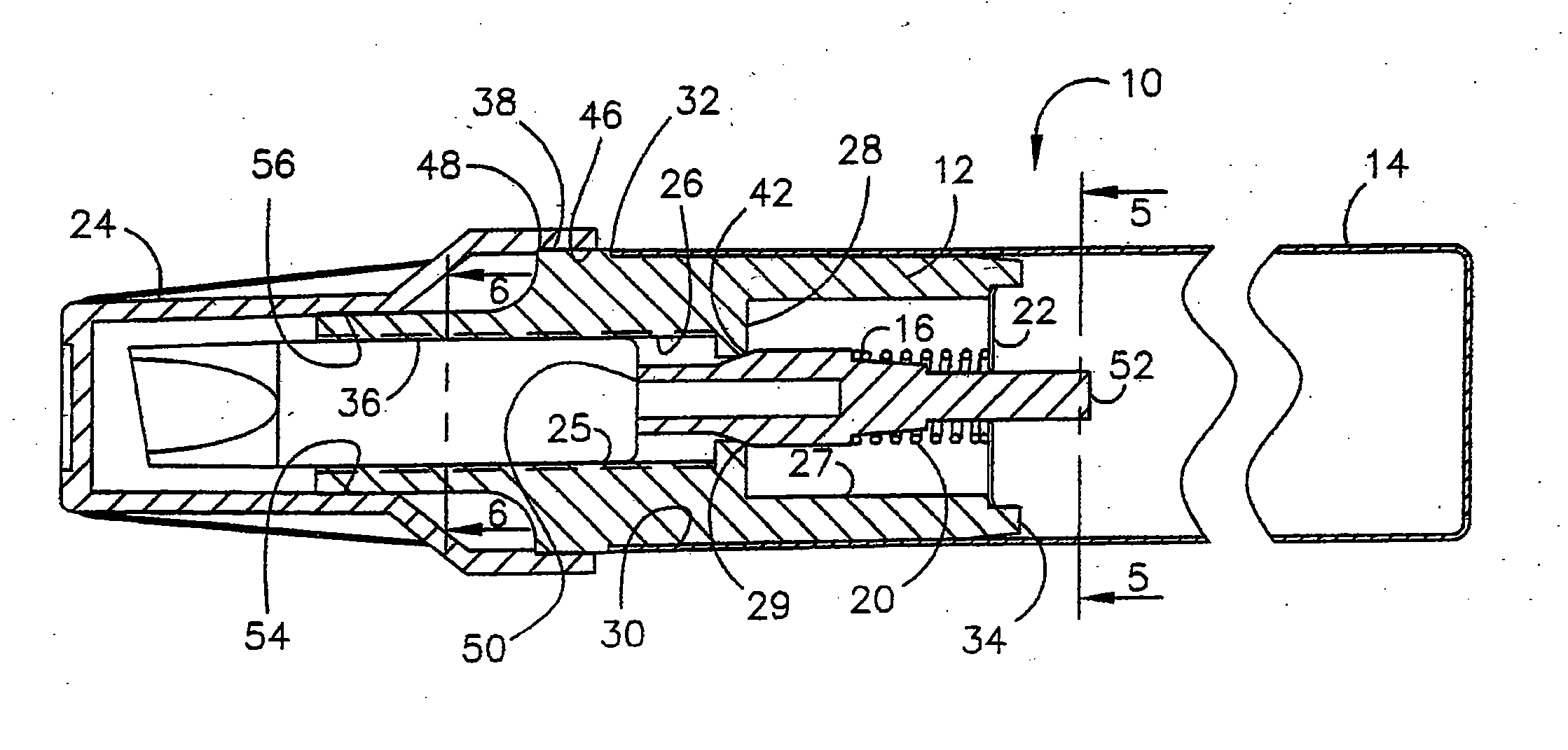
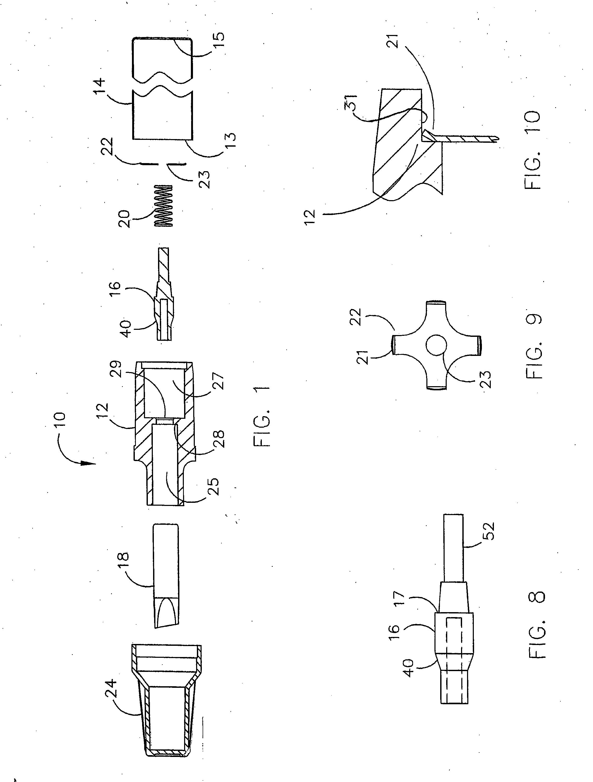
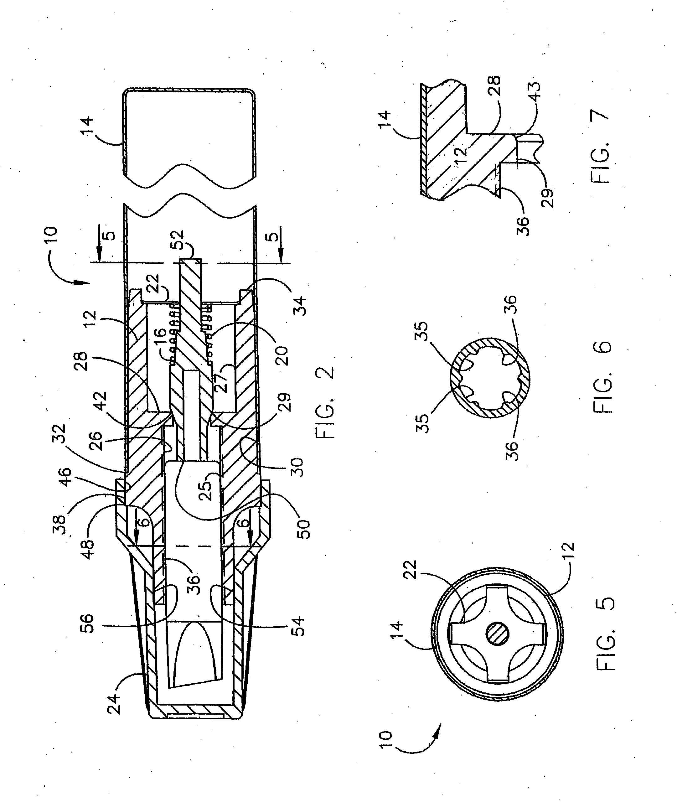
[0034] Referring now by reference numerals to the drawings and first to FIG. lit will be understood that the liquid applicator 10 includes a unitarily formed, one-piece closure member 12 formed from hard plastic material such as acetal plastic which interfits the open end of a container 14. The container is a hollow cylinder having an open end 13 and a closed end 15 and is preferably of metal such as aluminum. Acetal plastic is impervious to most fluids and solvents.

[0035] The closure 12 includes a passage 26 therethrough having a partition or web 28 dividing the passage into first and second portions 25 and 27 communicating with each other by means of an opening 29. The opening 29 receives the front end of the valve element or plunger 16 in sliding relation and the socketed rear end of the closure 12 is provided with the fixedly attached retainer 22. A spring 20, constituting a bias means, is received on the rear end of the plunger 16 and engages the retainer 22. The front end of ...


PUM


Abstract

This liquid applicator (10) provides a container (14) having a valve assembly (50). The valve assembly (15) includes a unitary closure (12) having a passage with a partition (28) dividing the passage into first and second portions (26) and (27) providing a valve opening. A plunger (16) provides a valve element which has an intermediate tapered portion (29) received within the partition (42) opening to provide flow of liquid from the container (14). A spring (20) overfits the plunger (16) and engages a retainer (22) at the end of the closure (12) and a nib (18) interfits the closure first passage (25) to engage the plunger (16) to provide longitudinal movement of the plunger (16) to open the valve assembly (50) to dispense liquid from the container (14) and into the nib (18) when pressure is applied to move the plunger (16) out of the valve opening. A second embodiment includes a comparatively thin wall of the closure (112) adjacent the second chamber (127) and the retainer (122) may include a flange portion (131) for more evenly distributing the retainer load to the closure wall (127a) defining the second chamber (127).

Description

CROSS-REFERENCE TO RELATED APPLICATIONS [0001] This application is a continuation in part of application Ser. No. 11 / 245,858 filed on Oct. 7, 2005, the contents of which are expressly incorporated herein by reference.BACKGROUND OF THE INVENTION [0002] This invention relates generally to liquid applicators and particularly to applicators used to dispense paints, inks, stains, coating adhesives, cleaning compounds, and the like, through a valved nib. [0003] Applicators of the type under consideration have been used since the 1950's and up until the present have always used more than four primary components to be effective. [0004] When assembled, the components of a typical valve actuated applicator operate by pushing the nib inwardly by depressing the nib onto a hard surface. Depressing the nib onto such a surface moves the plunger or valve element backwards against spring action and fluid, primarily liquid, flows from container into the nib. When pressure is released the spring retur...

Claims


Application Information

Patent Timeline
IPC IPC(8): B43K5/00B43K8/06
CPCB43K5/1845B43M11/06B43K8/04B43K8/022B43K8/06B43K5/00
Inventor ZINITI, MARCO F.STAUB, GARRY L.KUTSCH, THOMAS J.
Owner U MARK
Features
  • Generate Ideas
  • Intellectual Property
  • Life Sciences
  • Materials
  • Tech Scout
  • Unparalleled Data Quality
  • Higher Quality Content
  • 60% Fewer Hallucinations
Learn More