Direct combustion steam generator

a direct combustion and steam generator technology, applied in the direction of combustion types, lighting and heating apparatus, borehole/well accessories, etc., can solve the problems of affecting the operation of the heater, the heating of the heater, and the annular metallic sleeves are particularly susceptible to severe thermal stress, and achieve high firing intensities and stabilize the flame

Active Publication Date: 2007-08-30
DIRECT COMBUSTION TECH
View PDF21 Cites 52 Cited by
  • Summary
  • Abstract
  • Description
  • Claims
  • Application Information

AI Technical Summary

Benefits of technology

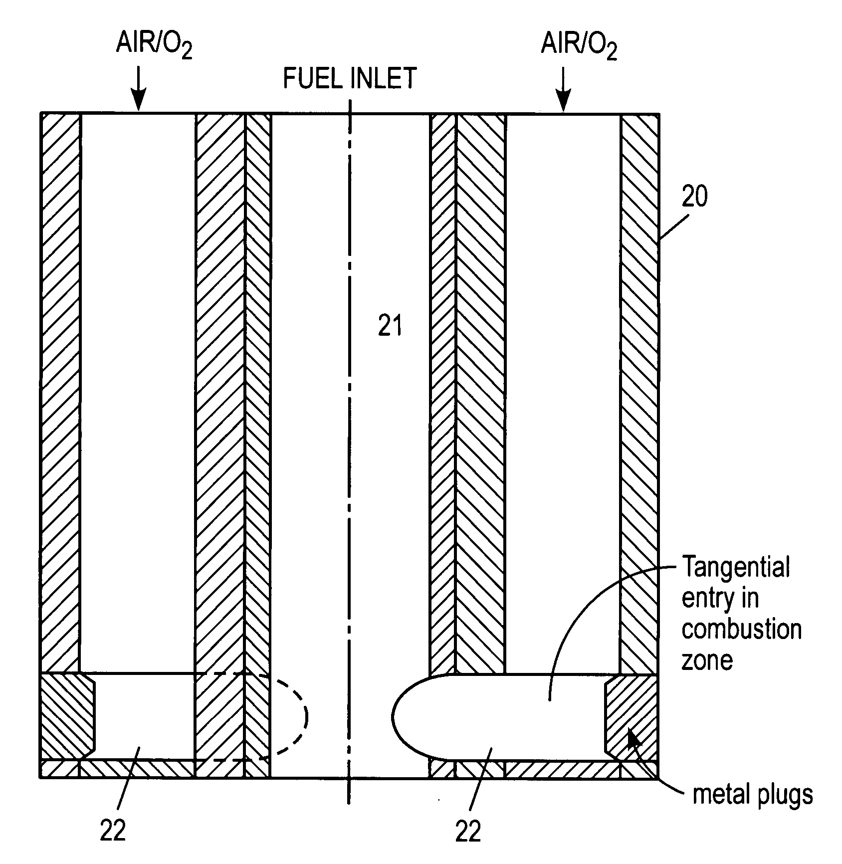
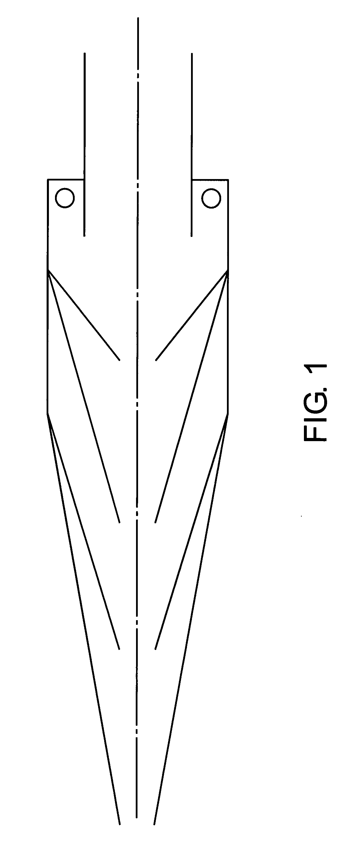
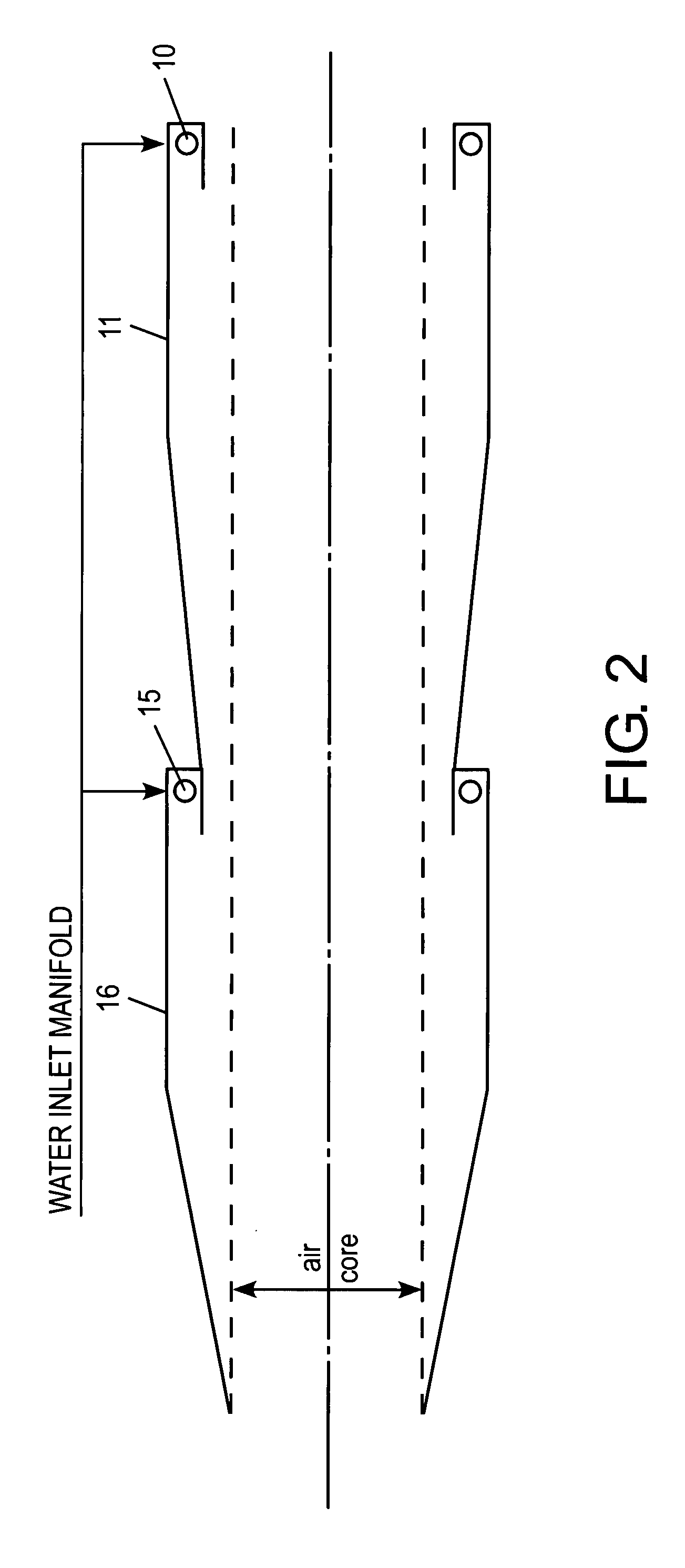
[0019] The present invention provides an apparatus for generating steam by directly heating water with a flame, the apparatus comprising a vortex container and a swirl burner. The vortex container has first and second ends, with a liquid inlet mounted through the wall of the container. The liquid inlet is adapted to tangentially inject liquid, in this case water, into the container to create a spiraling flow of the water within the vortex container. The container also has a vortex sustaining inner surface adapted to receive the water injected from the inlet, with the surface defining a vortex chamber which is axially aligned within the container. The apparatus also comprises a burner comprised of a metal block with an axial hole for supplying fuel and at least one tangential inlet hole for supplying air, enriched air or oxygen. The tangential supply of air creates a vortex recirculation zone where the hot gases from the flame are recirculated back to the base of the flame thereby providing a continuous source of ignition of the injected fuel. This recirculation stabilizes the flame at high firing intensities. The apparatus also comprises an outlet at the second end of the container along its axis for receiving a flow of liquid and gas exiting from the vortex chamber.

Problems solved by technology

Such shielding elements are often susceptible to severe scaling and corrosion.
Similar problems are typical in the case of downhole steam generators for use in injecting heated water or steam into oil-bearing underground formations.
The annular metallic sleeves which surround the flame and transport water to the exhaust gas zone in downhole or surface heaters suffer particularly from severe thermal stress related problems of fatigue and cracking.
This can lead to metal fatigue and failure of the mechanical integrity of the shroud wall.
The same fatigue and cracking problems arise when unquenched combustion exhaust gases are introduced into contact columns where direct contact cooling occurs.
However, the method as described therein is not of sufficient efficiency for generating steam.
If the inside tube walls become dry due to water evaporation, hotspots would result eventually causing tube rupture.
The only significant energy loss is the fuel energy used by the air compressor and is about 25% of the total energy consumption.
Another significant difference between the conventional surface steam generator (SSG) and the downhole steam generator (DSG) is the fact that a DSG injects all the gases of combustion into the formation along with the steam, while the SSG exhausts the gases to the atmosphere causing environmental problems.
Furthermore, the injection of gases downhole are known to reduce air quality problems associated with the surface steam generators.
Thus, enormous temperature differences occur across the thickness of these walls resulting in severe thermal stresses.
Therefore, the field tests conducted using this design have reported severe metal damage in the flame zone, which resulted in shutdown of the DSG in just 65 hours of operation.
The thermal stresses were also responsible for the severe cracking and consequent corrosion of the burner components used in the field tests.
These problems are still being tackled, and appear to be the main hurdle for this technology to be accepted by the oil recovery industry.
The process described in the '988 patent does not have this problem of severe thermal stresses in metal walls, which has been the source of major operating problems of other DSG designs.
As noted earlier, however, the process described in the '988 patent is not of sufficient efficiency for generating steam.

Method used


Image

  • Direct combustion steam generator
  • Direct combustion steam generator
  • Direct combustion steam generator

Examples


Embodiment Construction

[0028] The concept and the detailed development of the heat transfer process for heating water, i.e., direct heating of the water with a premix linear flow burner flame, are provided in U.S. Pat. No. 4,604,988, which is hereby incorporated herein in its entirety. The design presented therein is sufficient for heating large quantities of water very quickly. However, the method as described is not of sufficient effectiveness and efficiency for generating steam from water.

[0029] The additional requirements of steam / CO2 generation using the direct heating process are:

[0030] (1) The burner should be capable of supplying the latent heat of vaporization corresponding to the pressure of operation by burning sufficient fuel (in air or oxygen) in a manner that assures the aerodynamic stability of the high-intensity flame.

[0031] (2) The hydrocyclone should be capable of flowing an amount of water that is larger than the amount of steam generated (to account for varying steam quality needs) ...


PUM


Abstract

A method and apparatus for generating steam by heating water with a flame is provided. The water is introduced into a vortex sustaining container and flows through the container in a spiraling manner creating a liquid vortex with an open axial core. The flame effects heat transfer and is the product of the ignition of fuel mixed with a tangentially swirling oxygen containing gas.

Description

CROSS REFERENCE TO RELATED APPLICATION [0001] This application claims the benefit of U.S. Provisional Application No. 60 / 757,030, filed on Jan. 9, 2006, and is incorporated herein by reference in its entirety.BACKGROUND OF THE INVENTION [0002] 1. Field of the Invention [0003] This invention relates to an apparatus and method by which streams of gas and liquid may be introduced into a contact zone in a controlled manner in order to facilitate physical or chemical reactions between the two flows. More particularly, this invention relates to the containment of a flame within a surrounding continuous surface of flowing liquid, and to means by which heat from the products of combustion may be transferred to a liquid. Particular applicability is found in generating steam in compact space. [0004] 2. Description of the Related Art [0005] It is often desirable to bring together a stream of gas with a stream of liquid in order that a chemical or physical reaction or mass transfer may take pla...

Claims


Application Information

Patent Timeline
Patent Type & Authority Applications(United States)
IPC IPC(8): F23D14/62
CPCE21B43/2406E21B43/2408F02C6/04F02C6/18F23C3/006Y02E20/344F23C2202/40F23D14/20F23D14/24F23D14/32F23D99/006F23C9/006F23D91/04
Inventor RAO, DANDINA N.
Owner DIRECT COMBUSTION TECH
Why Eureka
Try Eureka