

Method and apparatus for plastic working of hollow rack bar and hollow rack bar
a technology of hollow racks and hollow bars, applied in the direction of mechanical equipment, engine components, etc., can solve the problems of resource consumption efficiency reduction, increased production costs, and heavy products, and achieve the effect of increasing the degree of weight reduction and effective use of materials
- Summary
- Abstract
- Description
- Claims
- Application Information
AI Technical Summary
Benefits of technology
Problems solved by technology
Method used
Image

Examples
Embodiment Construction
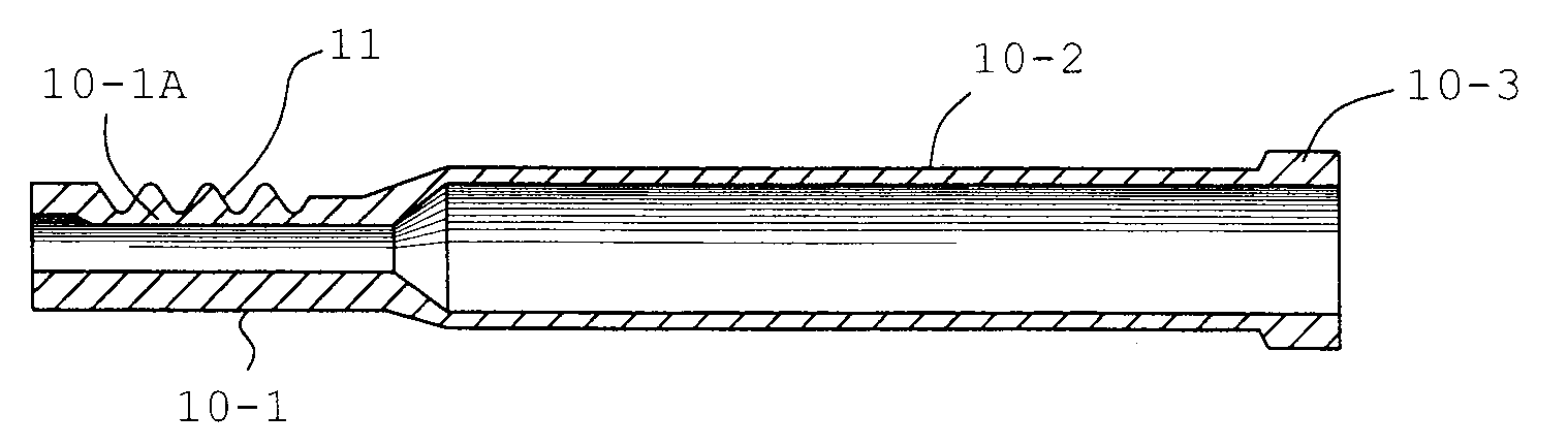
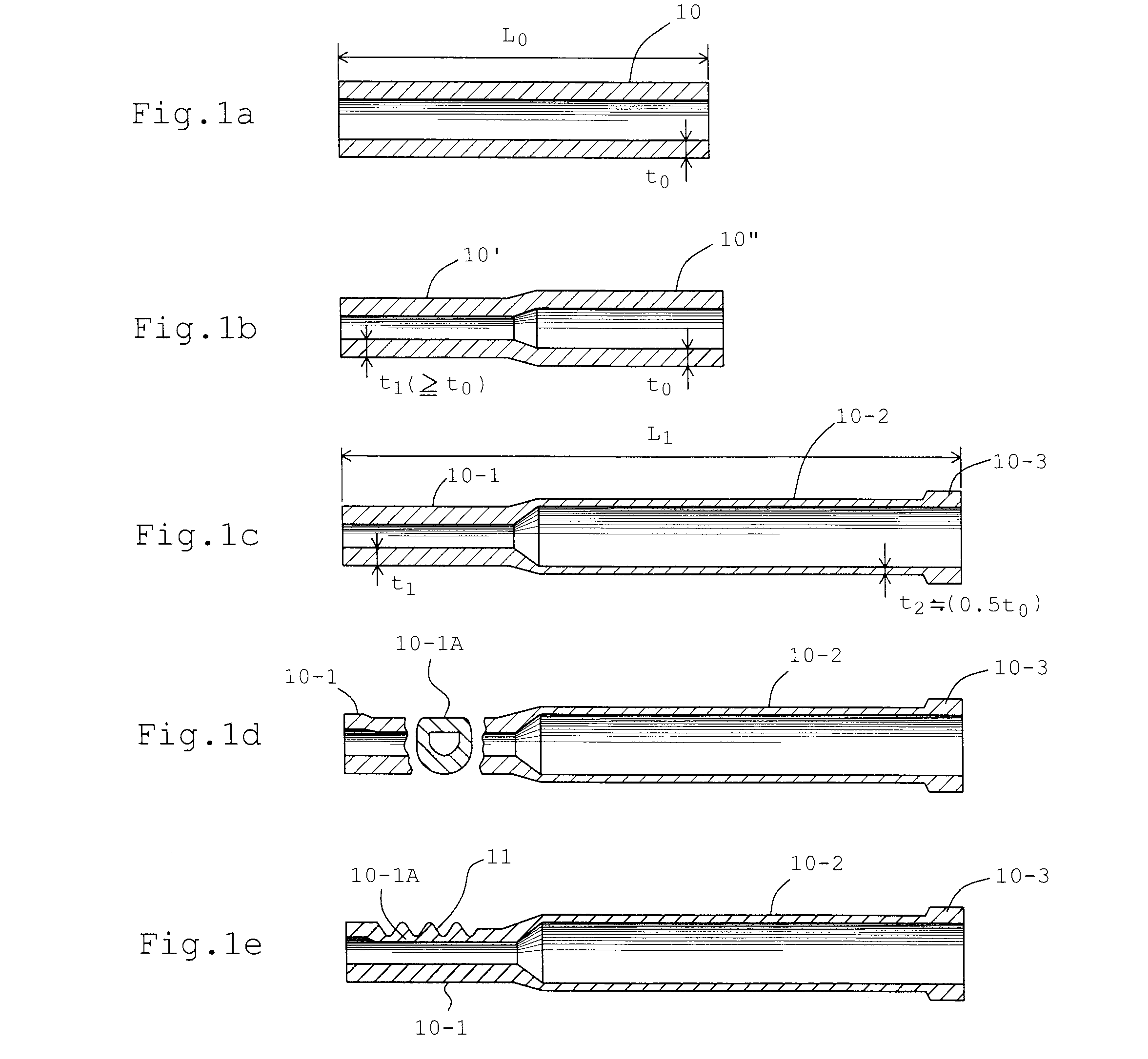
[0020]FIGS. 1a to 1e illustrates a series of steps or stages for forming a rack bar according to the present invention. In FIG. 1a, a reference numeral 10 denotes a blank pipe (intermediate part) or a work piece supplied from a maker after subjected to a phosphate coating process. In FIG. 1a, the wall thickness of a blank is designated by to and its length by L0, respectively. In this particular embodiment, the wall thickness t0 has a value of 4 mm, the material at a portion (tooth profile forming portion) of the blank pipe of this value of wall thickness is subjected to radially outwardly directed plastic flow, resulting in a formation of toothed portions of desired values of height and strength.
[0021]At a second step as shown in FIG. 1b, a first stage diameter reduction is done only at the tooth profile forming portion. Namely, at the location 10′ of the blank pipe of a predetermined length from its left-hand end is subjected to a diameter reduction, so that the wall thickness t1 ...
PUM
| Property | Measurement | Unit |
|---|---|---|
| Thickness | aaaaa | aaaaa |
| Diameter | aaaaa | aaaaa |
| Length | aaaaa | aaaaa |
Abstract
Description
Claims
Application Information