Automated steerable hole enlargement drilling device and methods

Active Publication Date: 2007-09-06
BAKER HUGHES INC
View PDF99 Cites 74 Cited by
  • Summary
  • Abstract
  • Description
  • Claims
  • Application Information

AI Technical Summary

Benefits of technology

[0010]In one operating mode, the drill string, together with the BHA described above, is conveyed into the wellbore. Drilling fluid pumped from the surface via the drill string energizes the drilling motor, which then rotates the drill bit to drill the wellbore. The drill string itself may be maintained substantially rotationally stationary to prevent damage to the interior surfaces of the drilled wellbore

Problems solved by technology

For instance, in some applications, constraints on wellbore geometry during drilling may result in a relatively small annular space in which cem

Method used


Image

  • Automated steerable hole enlargement drilling device and methods
  • Automated steerable hole enlargement drilling device and methods
  • Automated steerable hole enlargement drilling device and methods

Examples


Embodiment Construction

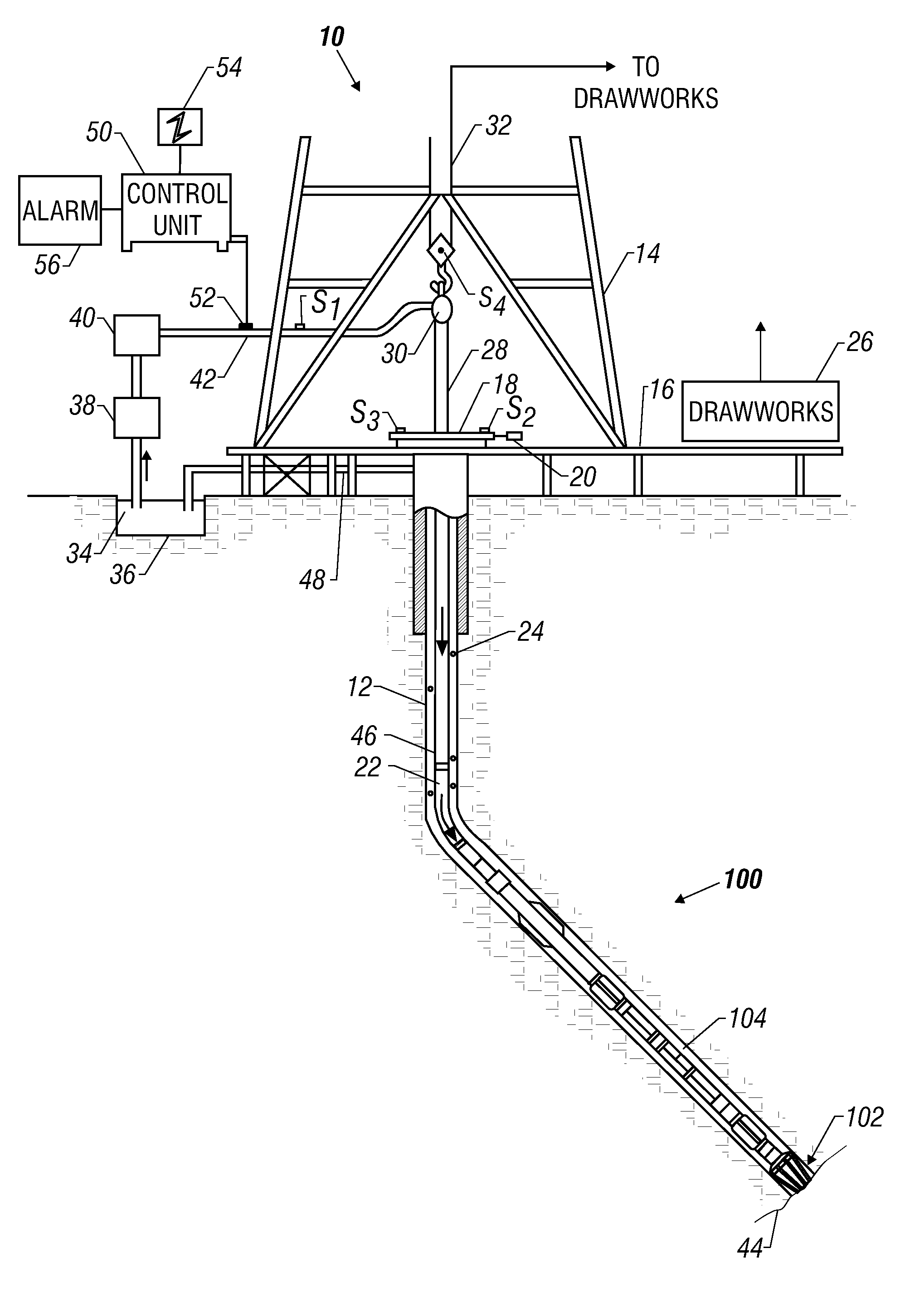
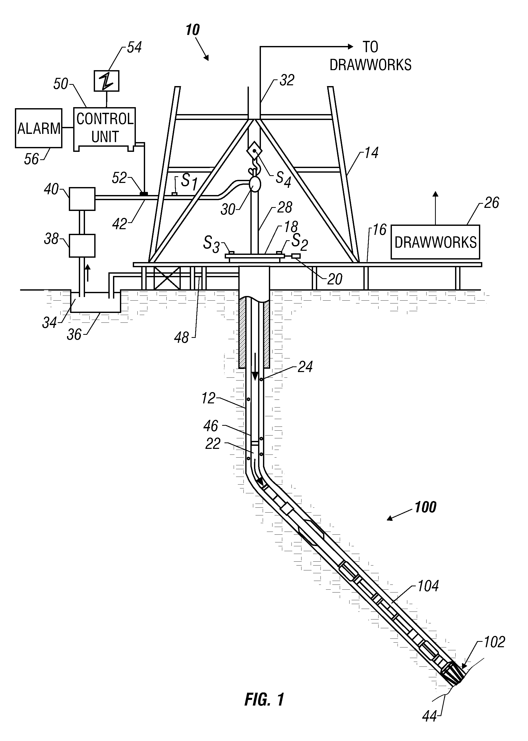
[0017]The present disclosure relates to devices and methods for drilling wellbores with one or more pre-selected bore diameter. The teachings of the present disclosure may be advantageously applied to “sliding” drilling operations that are performed by an automated drilling assembly. It will be understood, however, that the present disclosure may be applied to numerous other drilling strategies and systems. The present disclosure is susceptible to embodiments of different forms. There are shown in the drawings, and herein will be described in detail, specific embodiments of the present disclosure with the understanding that the present disclosure is to be considered an exemplification of the principles of the disclosure, and is not intended to limit the disclosure to that illustrated and described herein.

[0018]Referring initially to FIG. 1, there is shown an embodiment of a drilling system 10 utilizing a drilling assembly or bottomhole assembly (BHA) 100 made according to one embodi...


PUM


Abstract

A bottomhole assembly (BHA) coupled to a drill string includes a steering device, one or more controllers, and a hole enlargement device that selectively enlarges the diameter of the wellbore formed by the drill bit. In an automated drilling mode, the controller controls drilling directing by issuing instructions to the steering device. In one arrangement, the hole enlargement device is integrated into a shaft of a drilling motor that rotates the drill bit. The hole enlargement device includes an actuation unit and an electronics package that cooperate to translate extendable cutting elements between a radially extended position and a radially retracted position. The electronics package may be responsive to a signal that is transmitted from a downhole and/or a surface location. The hole enlargement device may also include one or more position sensors that transmit a position signal indicative of a radial position of the cutting elements.

Description

CROSS-REFERENCE TO RELATED APPLICATIONS[0001]This application takes priority from U.S. Provisional Application Ser. No. 60 / 778,329 filed Mar. 2, 2006.BACKGROUND OF THE DISCLOSURE[0002]1. Field of the Disclosure[0003]This disclosure relates generally to oilfield downhole tools and more particularly to modular drilling assemblies utilized for drilling wellbores having one or more enlarged diameter sections.[0004]2. Description of the Related Art[0005]To obtain hydrocarbons such as oil and gas, boreholes or wellbores are drilled by rotating a drill bit attached to the bottom of a drilling assembly (also referred to herein as a “Bottom Hole Assembly” or (“BHA”). The drilling assembly is attached to the bottom of a tubing or tubular string, which is usually either a jointed rigid pipe (or “drill pipe”) or a relatively flexible spoolable tubing commonly referred to in the art as “coiled tubing.” The string comprising the tubing and the drilling assembly is usually referred to as the “dril...

Claims


Application Information

Patent Timeline
IPC IPC(8): E21B7/04
CPCE21B7/06E21B47/12E21B10/322E21B10/32E21B10/327
Inventor TREVIRANUS, JOACHIMFREYER, CARSTENOPPELAAR, HANS-ROBERT
Owner BAKER HUGHES INC
Why Eureka
Try Eureka