Speed changing gearbox with dual path input

a technology of speed-changing gearboxes and inputs, applied in mechanical equipment, transportation and packaging, gearboxes, etc., can solve the problems of reducing peripheral speed, reducing power supply, and reducing the use of gearboxes, so as to reduce peripheral speed and save weight. , the effect of not only being small

Inactive Publication Date: 2007-09-06
KAREM AIRCRAFT INC
View PDF39 Cites 34 Cited by
  • Summary
  • Abstract
  • Description
  • Claims
  • Application Information

AI Technical Summary

Benefits of technology

[0008]It should be especially appreciated that power-dividing gear drives, particularly in rotorcraft, produce a series of benefits which translate into significant weight savings. When gear sizes are reduced (by virtue of splitting the torque from one path to two parallel paths of gear trains), the size not only of the gears but of their support bearings and the surrounding casing is reduced. Moreover, lower peripheral speeds result at the same rotational speed, and efficiency rises. The inventive subject matter integrates the speed-changing facility with the benefits of a dual-path drive.

Problems solved by technology

However, where an aircraft becomes relatively large, requiring several thousands of horsepower, the design of the speed-changing gearbox poses significant technical challenges.
Unfortunately, known automobile gearboxes fail to yield any useable design which would approach the power-to-weight ratio required in recent highly-efficient aircraft designs that typically demand a flight-weight, two-speed, multi-thousand horsepower-capable, highly-reliable gearbox.
However, when the device is called on to transmit many thousands of foot-pounds of torque, the components, particularly the clutch members, become large and heavy.
Gearsets rotating as a body with no relative gear rotation, i.e. with individual gear teeth carrying load but with no mesh action, can suffer tooth contact area degradation, and are therefore not suitable for long-term operation.
Therefore, these friction clutch / over-running clutch combinations will typically fail under heavy torque conditions.
However, the operation of a multi-thousand horsepower friction clutch at high rotational speed and the provision of a workable clamping / un-clamping arrangement is a technical challenge unlikely to be met successfully within a strict weight budget for aircraft gearboxes.

Method used


Image

  • Speed changing gearbox with dual path input
  • Speed changing gearbox with dual path input
  • Speed changing gearbox with dual path input

Examples


Embodiment Construction

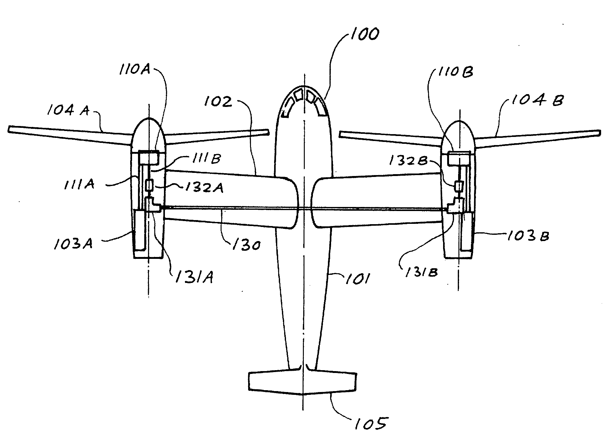
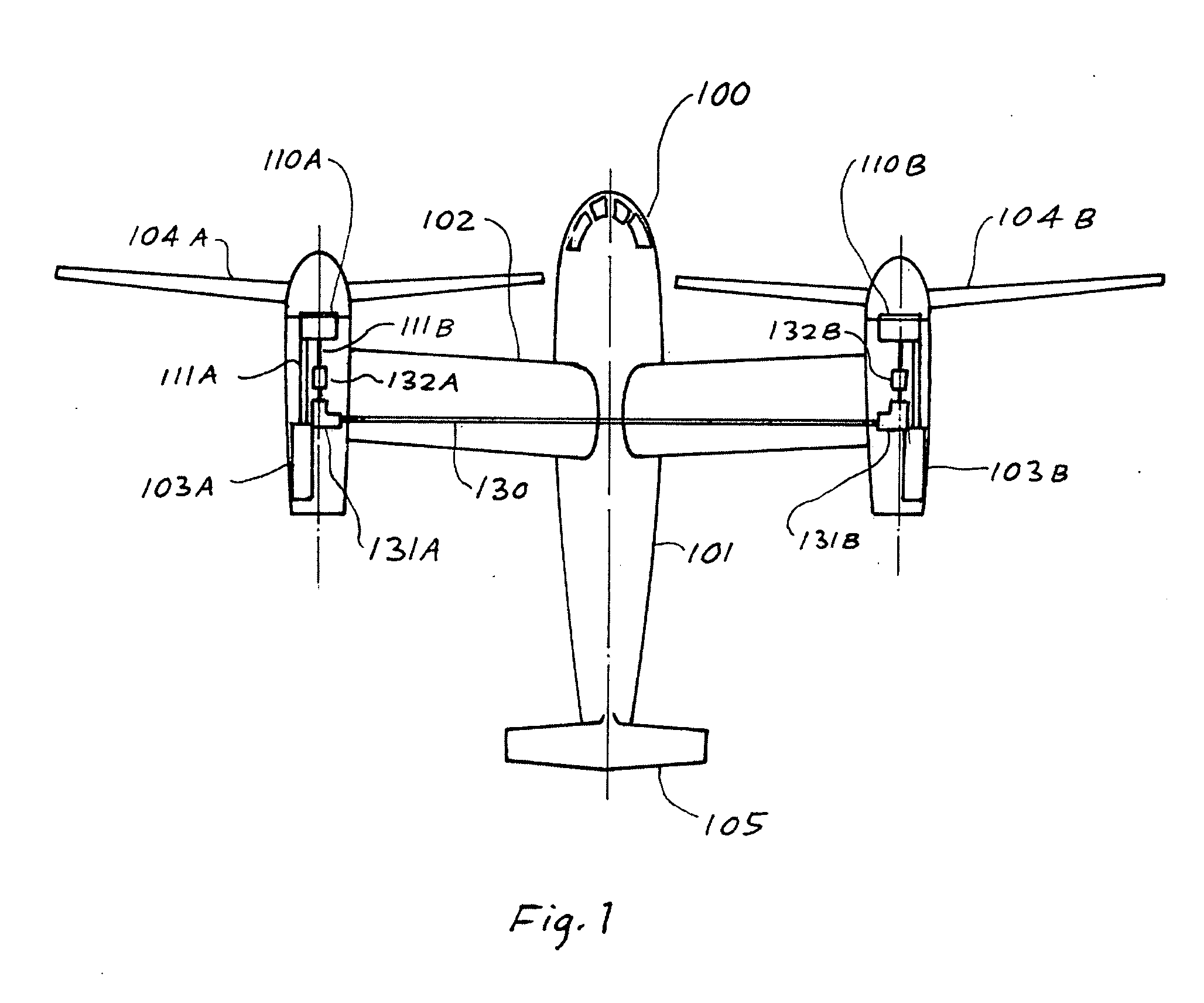
[0013]A typical tilt rotor aircraft is depicted in FIG. 1 in which rotorcraft 100 includes fuselage 101, a transverse wing 102, tail 105, left and right engines 103A and 103B, with left and right rotors 104A and 104B, respectively. Left and right gearboxes 110A and 110B are rotatably coupled via cross-wing drive shaft 130, angle drives 131A and 131B, and separable under-load couplings 132A and 132B. Shafts 11A and 11B transmit power from the engines to the rotors. Although the rotorcraft 100 in FIG. 1 is shown as an airplane having two tilt rotors, it should be understood that rotorcraft 100 is emblematic of any sort of vehicle, including fan boats, high speed marine drives, and particularly to vehicles where extreme reliability is important.

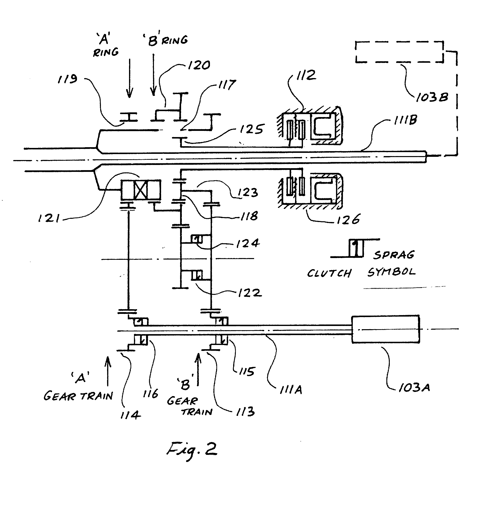
[0014]In FIG. 2, the gearbox generally comprises a first input from engine 103A via input shaft 111A, and a second input / output to / from engine 103B via shaft 111B. FIG. 2 shows that the basic arrangement of the input and output sections of the g...


PUM


Abstract

Contemplated gearboxes provide first and second power-balanced paths in which a speed changer is configured to operate with only one path. Most preferably, the gearbox includes a friction clutch and a sprag clutch arranged such that, together with a layshaft and spur-gear differential, gear shifting can be done while transmitting power.

Description

[0001]This application claims the benefit of our U.S. provisional patent application with the Ser. No. 60 / 693,723, which was filed Jun. 24, 2005.FIELD OF THE INVENTION[0002]The field of the invention relates to the transmission of power by gears, and to the provision of a speed changing facility within the gearbox.BACKGROUND OF THE INVENTION[0003]There are some instances in the configuration of aircraft where the rotational speed of the propeller, in the case of a fixed wing aircraft, or of the rotor, in the case of a helicopter, has to be changed relative to the speed of the engine. This is because the range of speed of the propeller or rotor required for good efficiency exceeds the permissible speed range of commonly-used turboshaft engines. Hence a two-speed, lightweight reduction gearbox is required. The aircraft type which would benefit from a two-speed propeller drive is a high-altitude, long-endurance machine. Similarly, in the case of rotorcraft or for tilt-rotor aircraft wh...

Claims


Application Information

Patent Timeline
Patent Type & Authority Applications(United States)
IPC IPC(8): B64C27/08
CPCF16H37/0833B64D35/04
Inventor WAIDE, WILLIAM MARTIN
Owner KAREM AIRCRAFT INC
Why Eureka
Try Eureka