Magnifying optical system for endoscope

an optical system and endoscope technology, applied in the field of magnification optical system for endoscope, can solve the problems of short depth, inability to obtain desired image quality, inability to meet the demand for high image quality, etc., and achieve the effect of preserving sufficient observation depth and high quality

Active Publication Date: 2007-09-06
OLYMPUS CORP
View PDF3 Cites 26 Cited by
  • Summary
  • Abstract
  • Description
  • Claims
  • Application Information

AI Technical Summary

Benefits of technology

[0028]The magnifying optical systems for endoscope according to the present invention which have the above described compositions allow F numbers to be changed little between usual observing conditions and conditions for observing magnified images, are capable of reserving sufficient observation depths in any observing condition and provide images of high qualities.

Problems solved by technology

Accordingly, arrangement of picture elements in a larger number of an image pickup device may result in an insufficient observation depth of an image pickup optical system, thereby making it impossible to obtain a desired image quality.
When the conventional optical system disclosed by these patent publications are used in combination with image pickup device on which picture elements are arranged in large numbers, the optical systems will have too small F numbers in the usual observing conditions even if the F numbers are reduced to the diffraction limit, thereby having short depths and posing problems in practical use.
Accordingly, this optical system allows aberrations to be changed remarkably between a usual observing condition and a condition for observing a magnified image, and cannot meet a demand for a high image quality.
This optical system allows a remarkable change of chromatic aberration in particular which is a cause of image color oozing.
However, an optical system of this type allows an F number to be changed remarkably between a usual observing condition and a condition for observing a magnified image, thereby posing a problem which is similar to those posed by the optical systems disclosed by Japanese Patent Kokoku Publication No.
Sho 61-44283 discloses an objective lens system for endoscope having a high magnification, which is problematic for practical use since the optical system has a narrow visual field in a usual observing condition, thereby making it difficult to perform such works as screening interiors of living bodies for finding morbid portions, treatment of the morbid portions and the like.

Method used


Image

  • Magnifying optical system for endoscope
  • Magnifying optical system for endoscope
  • Magnifying optical system for endoscope

Examples


first embodiment

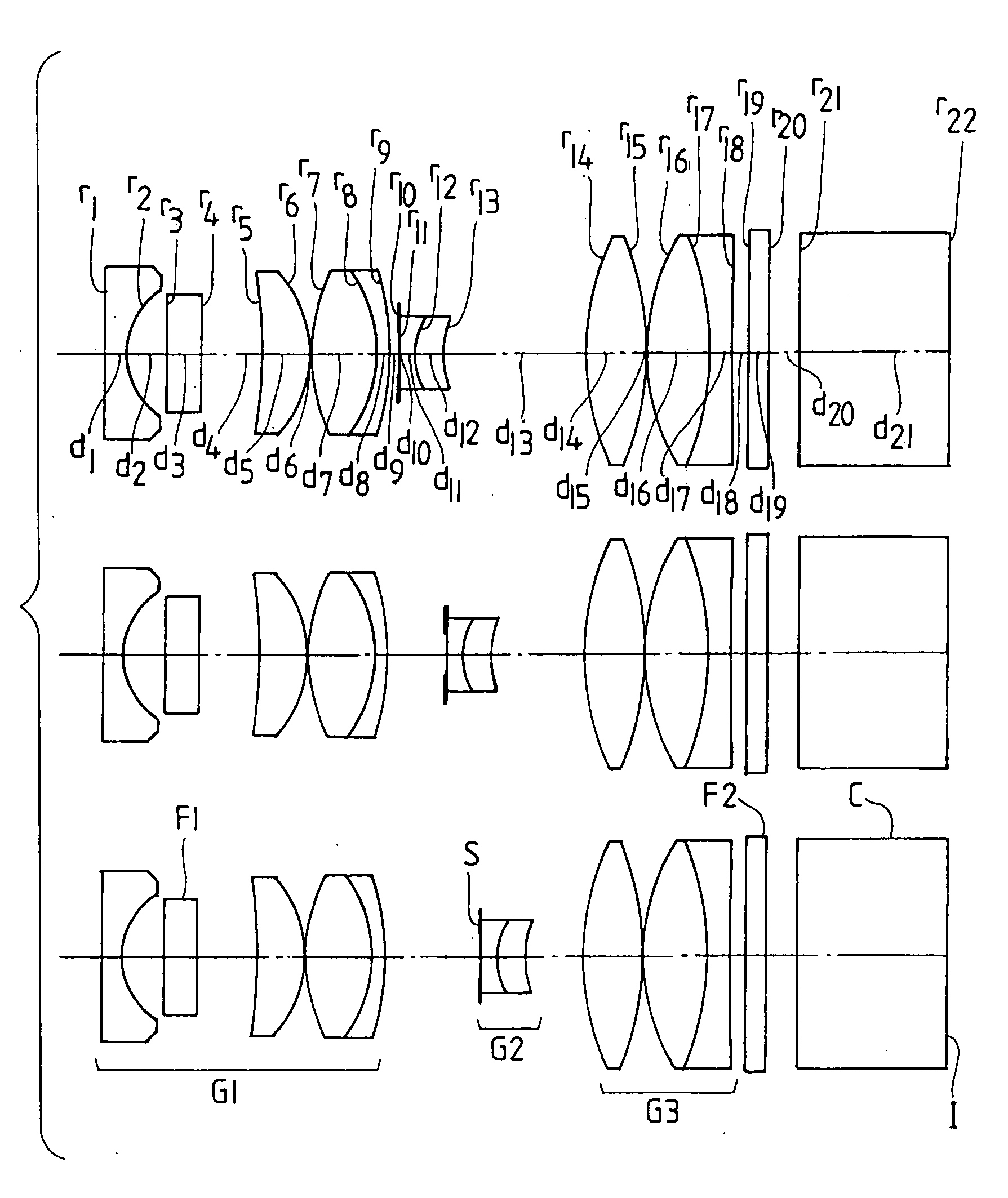
[0103]the magnifying optical system for endoscope according to the present invention is an optical system which has a composition illustrated in FIG. 1 and the following numerical data:

(object surface)d0 = D0r1 = ∞d1 = 0.36n1 = 1.88300ν1 = 40.78r2 = 1.297d2 = 0.73r3 = ∞d3 = 0.62n2 = 1.51400ν2 = 75.00r4 = ∞d4 = 1.13r5 = −8.3111d5 = 0.88n3 = 1.48749ν3 = 70.23r6 = −1.980d6 = 0.01r7 = 3.240d7 = 1.20n4 = 1.51633ν4 = 64.14r8 = −2.332d8 = 0.24n5 = 2.00330ν5 = 28.27r9 = −4.319d9 = D1r10 = ∞ (stop)d10 = 0.02r11 = ∞d11 = 0.28n6 = 1.48749ν6 = 70.23r12 = 1.257d12 = 0.52n7 = 1.59270ν7 = 35.31r13 = 1.927d13 = D2r14 = 4.593d14 = 1.08n8 = 1.48749ν8 = 70.23r15 = −5.372d15 = 0.02r16 = 3.767d16 = 1.19n9 = 1.51633ν9 = 64.14r17 = −4.774d17 = 0.42n10 = 1.92286ν10 = 18.90r18 = 52.579d18 = 0.29r19 = ∞d19 = 0.40n11 = 1.52287ν11 = 59.89r20 = ∞d20 = 0.56r21 = ∞d21 = 2.75n12 = 1.51633ν12 = 64.14r22 = ∞

Condition for observingUsual observingmagnified image of objectconditionIntermediateat short distance(wide pos...

second embodiment

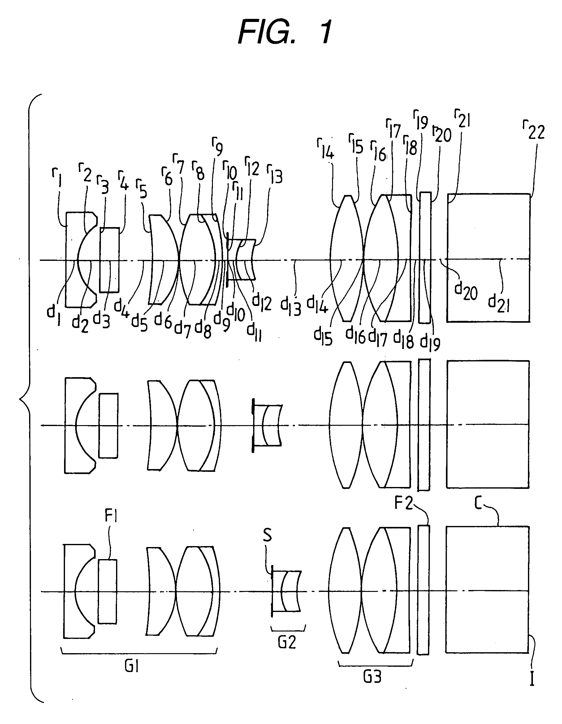
[0113]the magnifying optical system for endoscope according to the present invention has a composition illustrated in FIG. 2 and the following numerical data:

(object surface)d0 = D0r1 = ∞d1 = 0.36n1 = 1.88300ν1 = 40.78r2 = 1.246d2 = 0.73r3 = ∞d3 = 0.62n2 = 1.51400ν2 = 75.00r4 = ∞d4 = 0.50n3 = 1.52287ν3 = 59.89r5 = ∞d5 = 0.57r6 = 31.448d6 = 0.88n4 = 1.48749ν4 = 70.23r7 = −2.017d7 = 0.05r8 = 3.576d8 = 1.20n5 = 1.48749ν5 = 70.23r9 = −1.879d9 = 0.24n6 = 1.84666ν6 = 23.78r10 = −3.339d10 = D1r11 = ∞ (stop)d11 = 0.02r12 = ∞d12 = 0.28n7 = 1.48749ν7 = 70.23r13 = 1.678d13 = 0.52n8 = 1.84666ν8 = 23.78r14 = 1.703d14 = D2r15 = 19.018d15 = 1.29n9 = 1.48749ν9 = 70.23r16 = −2.749d16 = 0.02r17 = 2.793d17 = 1.22n10 = 1.60311ν10 = 60.64r18 = −9.649d18 = 0.42n11 = 1.92286ν11 = 18.90r19 = 4.696d19 = 0.87r20 = ∞d20 = 1.60n12 = 1.51633ν12 = 64.14r21 = ∞

Condition for observingUsual observingmagnified image of objectconditionIntermediateat short distance(wide position)condition(tele position)D018.003.381.80...

third embodiment

[0123]the optical system according to the present invention has a composition illustrated in FIG. 3 and the following numerical data:

(object surface)d0 = D0r1 = ∞d1 = 0.45n1 = 1.88300ν1 = 40.78r2 = 1.886d2 = 1.00r3 = ∞d3 = 0.57n2 = 1.52287ν2 = 59.89r4 = ∞d4 = 0.47r5 = −6.999d5 = 2.75n3 = 1.69895ν3 = 30.13r6 = −3.383d6 = D1r7 = 3.920d7 = 0.61n4 = 1.88300ν4 = 40.76r8 = 9.496d8 = D2r9 = ∞ (stop)d9 = 0.09r10 = 33.957d10 = 0.27n5 = 1.84666ν5 = 23.78r11 = 1.805d11 = 2.03n6 = 1.51633ν6 = 64.14r12 = −6.057d12 = 0.08r13 = 5.501d13 = 1.09n7 = 1.88300ν7 = 40.76r14 = 3.662d14 = 0.77n8 = 1.80100ν8 = 34.97r15 = −15.338d15 = 1.82r16 = ∞d16 = 2.00n9 = 1.51400ν9 = 75.00r17 = ∞

Condition for observingUsual observingmagnified image of objectconditionIntermediateat short distance(wide position)condition(tele position)D023.5010.503.00D13.262.921.53D20.390.722.12flw1.4801.5371.825Fno9.109.109.10fW / fT = 1|f3 / f2| = 0.81|f2 / f1| = 0.36fT = 9.1βT = −0.4ω = 60.7°f3 / f1 = −0.29hT / hW = 1.00Enp / flw = 1.33IH / (p × 10...


PUM


Abstract

A magnifying optical system for endoscope which can be set at least in a usual observing condition (at a wide position) and a condition for observing a magnified image of an object at a short distance (at a tele position) by moving any of one of lens units, and is configured so as to satisfy a condition mentioned below, thereby providing a sufficient observation depth in each observing condition:f(W) / F(T)>0.93  (1)

Description

BACKGROUND OF THE INVENTION [0001]1. Field of the Invention[0002]The present invention relates to a magnifying optical system for endoscope, and more specifically an objective lens system (optical system) for endoscope which has a vari-focal function, thereby permitting observation of a magnified image.[0003]2. Description of the Prior Art[0004]In recent years, an increasing demand is posed in a medical field for an optical system which permits observation of a magnified image for precise diagnosis of a location which has changed to a morbid state.[0005]Optical systems which are disclosed by official patent publications mentioned below are known as conventional examples of optical system which permits observation of such a magnified image, and is of a type which consists of three positive, negative and positive lens units, and performs a magnification change and focusing by moving the second negative lens unit:[0006]Japanese Patent Kokoku Publication No. Sho-61-44283[0007]Japanese P...

Claims


Application Information

Patent Timeline
Patent Type & Authority Applications(United States)
IPC IPC(8): G02B15/14
CPCG02B15/173G02B23/2438G02B15/177G02B15/143105
Inventor TAKATO, HIDEYASU
Owner OLYMPUS CORP
Why Eureka
Try Eureka