Optical fibers and optical fiber devices with total dispersion greater than material dispersion

Inactive Publication Date: 2007-09-06
RAMACHANDRAN SIDDHARTH
View PDF7 Cites 43 Cited by
  • Summary
  • Abstract
  • Description
  • Claims
  • Application Information

AI Technical Summary

Benefits of technology

[0008] The present invention is directed to optical fiber devices incorporating optical fibers with refractive index profiles that yield Dtotal>Dm in any wavelength range such that Dtotal<+50 ps/nm-km, as would be desired in a variety of fiber devices exploiting optical nonlinearities. The aforementioned refractive index profile yields the given dispersion values when light resides substantially in a single higher order mode (HOM) of the fiber. Typically, this HOM would be the LP02 mode of

Problems solved by technology

However, the dispersion of air-silica fibers is closely tied to their modal areas, and it is not possible to achieve high dispersion as well as large effective modal areas—hence, this design space would be of limited use in systems requiring high positive dispersion but also low nonlinearities.
In addition, these fibers are known to have high birefringence and loss, both of which diminish their utility in practical systems.
These fibers also have termination problems—splices to other fibers lead to loss, changes in optical properties, and cannot be made reliably.
However, these designs do not enable achieving zero or low positive dispersion values in

Method used


Image

  • Optical fibers and optical fiber devices with total dispersion greater than material dispersion
  • Optical fibers and optical fiber devices with total dispersion greater than material dispersion
  • Optical fibers and optical fiber devices with total dispersion greater than material dispersion

Examples


Embodiment Construction

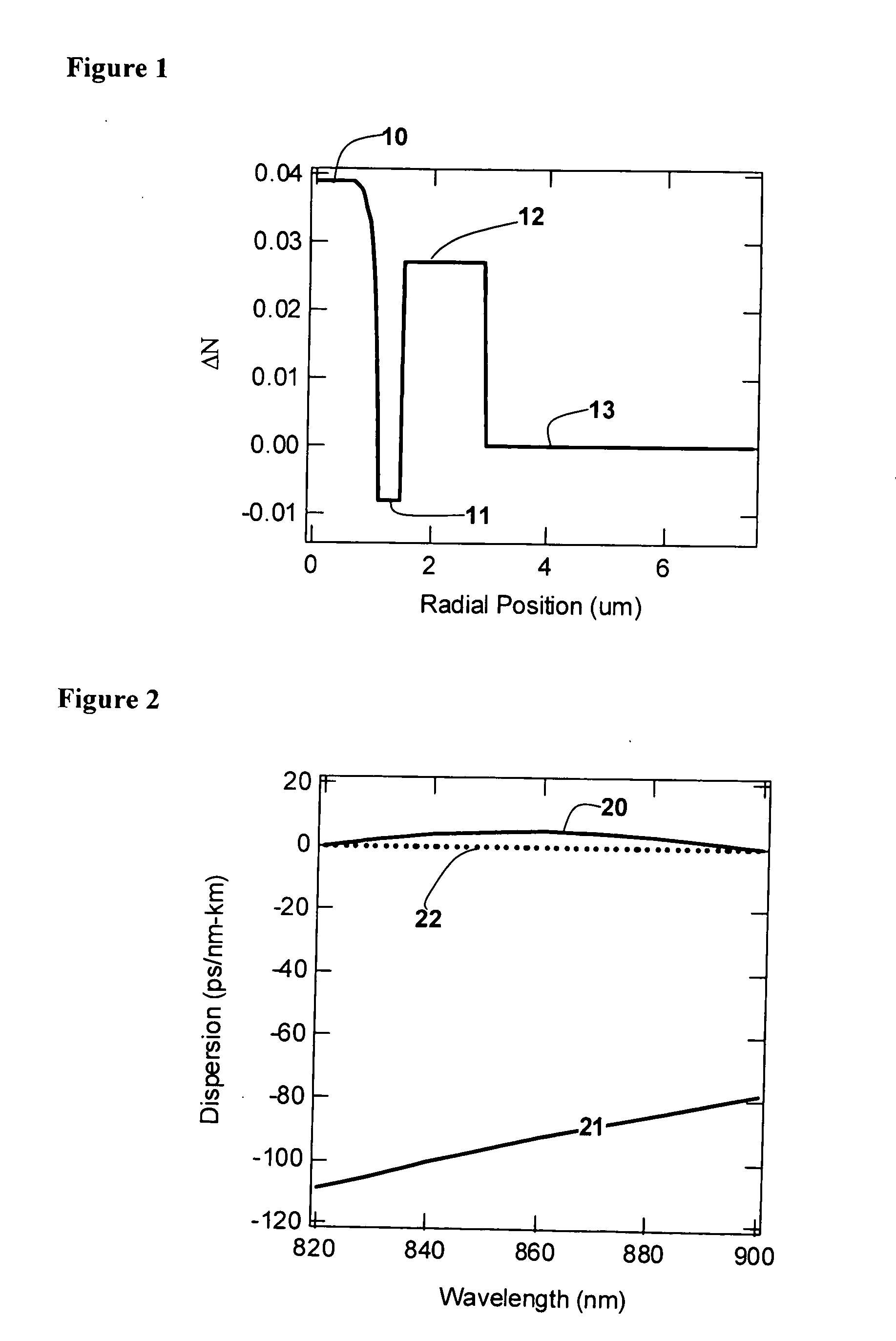
[0012]FIG. 1 shows the index profile of a fiber that supports more than one mode, but which is designed to yield desired the Dtotal for the LP02 mode. The refractive index profile comprises a core, 10, with ΔN of 0.039 extending to a radial position of 1 μm; followed by a trench region (down-doped ring), 11, with ΔN of −0.008 and a thickness of 0.5 □m; followed by an up-doped ring, 12, with ΔN of 0.027 and a thickness of 1.4 μm. Thereafter, the fiber cladding, consisting only of silica glass, 13, extends to the edge of the glass cladding of the fiber. For typical fibers, this extends to a radial position of 62.5 □m. The profile in FIG. 1 is shown only till a radial position of 7 μm because the rest of the fiber is merely an extension of the silica glass cladding. The refractive index profile is characterized in terms of ΔN, the difference in refractive index between the region of interest and the silica cladding.

[0013]FIG. 2 shows the dispersion as a function of wavelength, of the ...


PUM


Abstract

Disclosed are optical fiber devices incorporating optical fibers with total dispersion greater than material dispersion, and with preferred dispersion values less than +50 ps/nm-km. The desired dispersion values are obtained when light resides substantially in a single higher order mode (HOM) of the fiber, typically the LP02 mode. The optical fibers also preferably have substantial separation between the effective indices of the HOM and any other mode.

Description

FIELD OF THE INVENTION [0001] The invention relates to optical fibers devices wherein the total dispersion of the device is greater than the material dispersion. BACKGROUND OF THE INVENTION [0002] An optical fiber can guide light with multiple spatial patterns, each of which is uniquely designated as a transverse mode of the fiber (hereafter, called mode, for brevity). The dispersive characteristics of an optical signal in a fiber depend on the mode in which it is travelling. Thus, each mode may be characterised with a dispersion value specific to it. The dispersion of a mode is roughly equal to the sum of the material dispersion (Dm) and waveguide dispersion (Dw). The material dispersion is the dispersion of the material in which the optical signal resides—that is, the material of which the fiber is made (most commonly, Silica with trace amounts of Germanium, Phosphorus, Fluorine and other dopants). The waveguide dispersion is due to the refractive index profile that defines a fibe...

Claims


Application Information

Patent Timeline
IPC IPC(8): G02B6/02
CPCG02B6/02023G02B6/02095G02B6/02214G02B6/29374G02B6/03688G02B6/29317G02B6/03644
Inventor RAMACHANDRAN, SIDDHARTH
Owner RAMACHANDRAN SIDDHARTH
Why Eureka
Try Eureka