Method and apparatus for panoramic imaging

a panoramic imaging and camera technology, applied in the field of wide-angle imagery, can solve the problems of unnecessarily increasing the cost of imaging system, requiring expensive fisheye lens cameras, and images taken of moving vehicles with conventional cameras using such inexpensive cmos image sensors, and achieves the effect of little or no distortion and little distortion

Active Publication Date: 2007-09-06
GARMIN
View PDF19 Cites 198 Cited by
  • Summary
  • Abstract
  • Description
  • Claims
  • Application Information

AI Technical Summary

Benefits of technology

[0008] It is an object of the invention to provide a low-cost, wide-view imaging system that captures wide-view images from a moving platform, with little or no distortion. This object is achieved by providing an imaging method and system for capturing a wide-view image from a moving platform, using conventional, inexpensive sensor components. The images captured using the method and imaging system of the present invention show little distortion caused by the motion of the camera relative to the subject at the time of capture. Furthermore, the little distortion that is introduced has no discontinuities and can be compensated for during interpretation of the images.

Problems solved by technology

As few as two or four cameras could also be used, but these configurations would require cameras with fisheye lenses, which are costly.
A configuration of eight or ten cameras may also be used, but this may unnecessarily increase the cost of the imaging system.
Images taken of that moving vehicle with a conventional camera using such inexpensive CMOS image sensors will show distortion.
Furthermore, the amount of lean of an object depends on its distance from the camera, thus making the distortion impossible to correct in an automated post-processing of the image.
CMOS image sensors typically used in high-volume consumer applications have the advantage of low cost, but perform poorly in motion photography.
This is because this class of image sensors, unlike CCDs and more expensive CMOS devices, does not have memory behind each pixel or sensor element.

Method used


Image

  • Method and apparatus for panoramic imaging
  • Method and apparatus for panoramic imaging
  • Method and apparatus for panoramic imaging

Examples


Embodiment Construction

[0032] The present invention will now be described more fully in detail with reference to the accompanying drawings, in which the preferred embodiments of the invention are illustrated. This invention should not, however, be construed as limited to the embodiments set forth herein; rather, the illustrations are provided so that this disclosure will fully convey the scope of the invention to those skilled in the art.

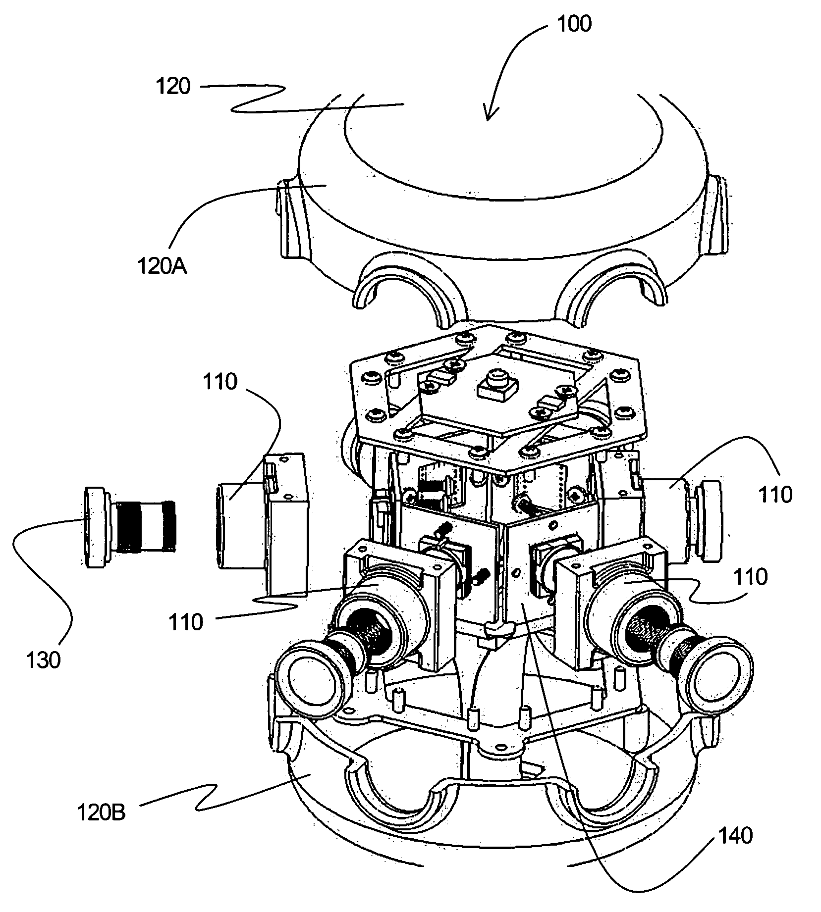
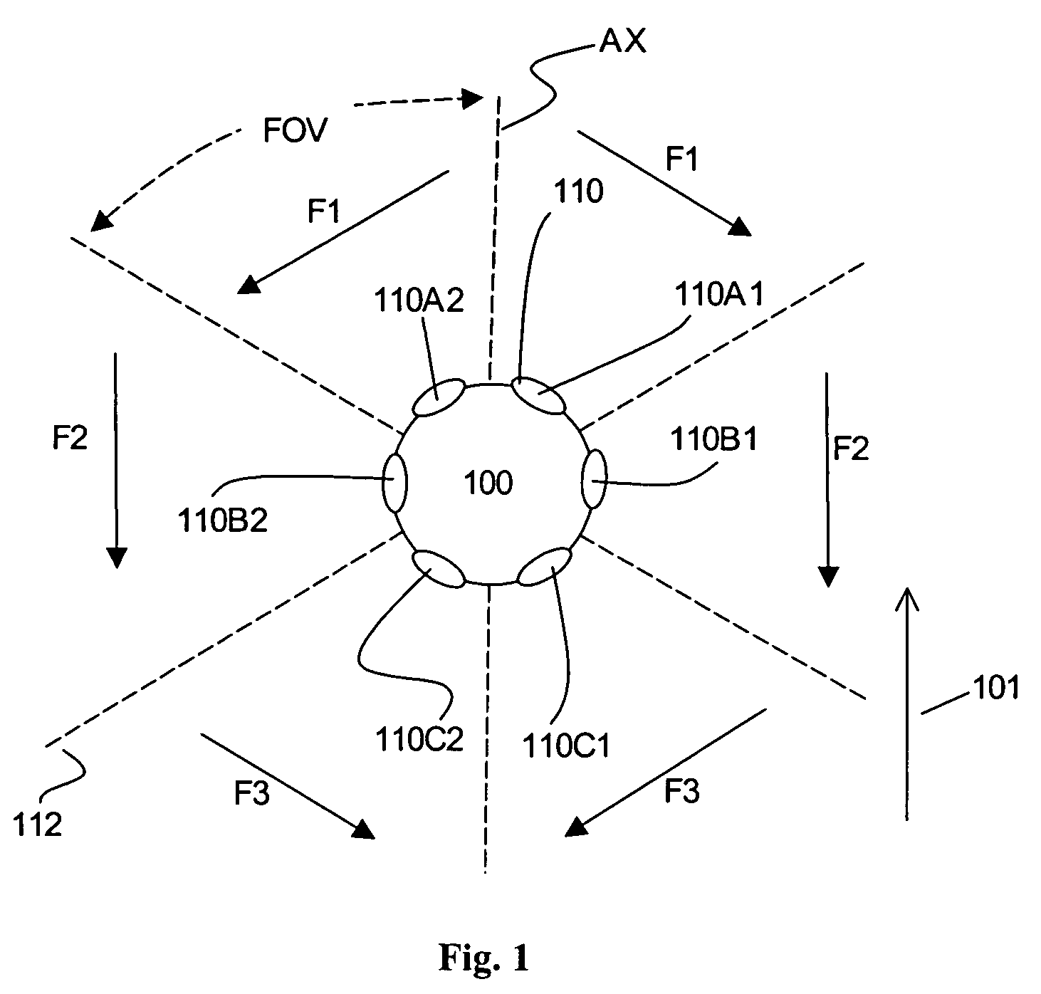
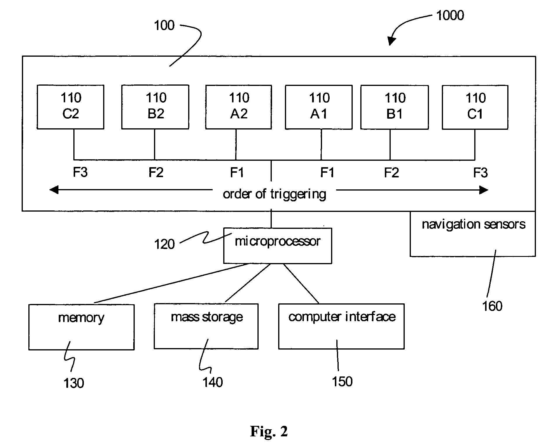
[0033]FIG. 1 is a top plane diagrammatic view of a compound camera 100 according to the invention. The compound camera 100 comprises a plurality of low-cost single cameras 110. In the Preferred Embodiment of the invention, the compound camera 100 has pairs of single cameras 110 arranged about an orientation axis AX as shown. The orientation axis AX is an imaginary line that extends from a first axis end at the front center position to a second axis end at the rear center position of the compound camera 100. In the embodiment shown, the pairs of single cameras 110 include...


PUM


Abstract

Camera system and methods to capture panoramic imagery from a camera mounted on a moving platform, using low-cost digital image sensors. The panoramic imagery appears seamless and natural to the eye. The panoramic imaging system and methods are specifically designed to accommodate the long acquisition times of low-cost digital image sensors, despite the motion of the camera during image capture. Pairs of cameras are arranged about an axis and a pairwise firing sequence enables capturing a series of adjacent images without gap or overlap. Additionally, when combined with suitable supplemental sensors, the image data provide location information about objects in the image for use in elementary photogrammetry.

Description

BACKGROUND INFORMATION [0001] 1. Field of the Invention [0002] The present invention relates to the field of wide-view imagery. More particularly, the invention relates to wide-view imagery captured from a moving platform. [0003] 2. Description of the Prior Art [0004] A variety of photographic systems that create panoramic images and even full spherical images are commercially available. Some of these systems use a single lens or mirror, such as the 0-360 One-Click Panoramic Optic. One disadvantage of such systems is that a lens or mirror creates the circular image. As a result, little more than half of the typically rectangular sensor is actually used. Furthermore, the resolution is limited to that of a single sensor—typically about 6 mega-pixel for reasonably high-end cameras. Other systems, such as immersive camera systems, stitch together pairs of hemispherical images captured with 180-degree fisheye lenses, correcting for the inherent distortion of such lenses. Having to use a ...

Claims


Application Information

Patent Timeline
Patent Type & Authority Applications(United States)
IPC IPC(8): G03B41/00
CPCG03B41/00H04N5/23238H04N5/2258H04N5/2253H04N23/45H04N23/54H04N23/698
Inventor DELORME, DAVID M.PETERSON, JAMES G.
Owner GARMIN
Why Eureka
Try Eureka