Electronic apparatus and projector

Active Publication Date: 2007-09-06
SEIKO EPSON CORP
View PDF2 Cites 4 Cited by
  • Summary
  • Abstract
  • Description
  • Claims
  • Application Information

AI Technical Summary

Benefits of technology

[0007]An advantage of some aspects of the invention is that it obtains an electronic apparatus in which a general remote control device no

Problems solved by technology

However, the remote control device having an ID code transmission f

Method used


Image

  • Electronic apparatus and projector
  • Electronic apparatus and projector
  • Electronic apparatus and projector

Examples


first embodiment

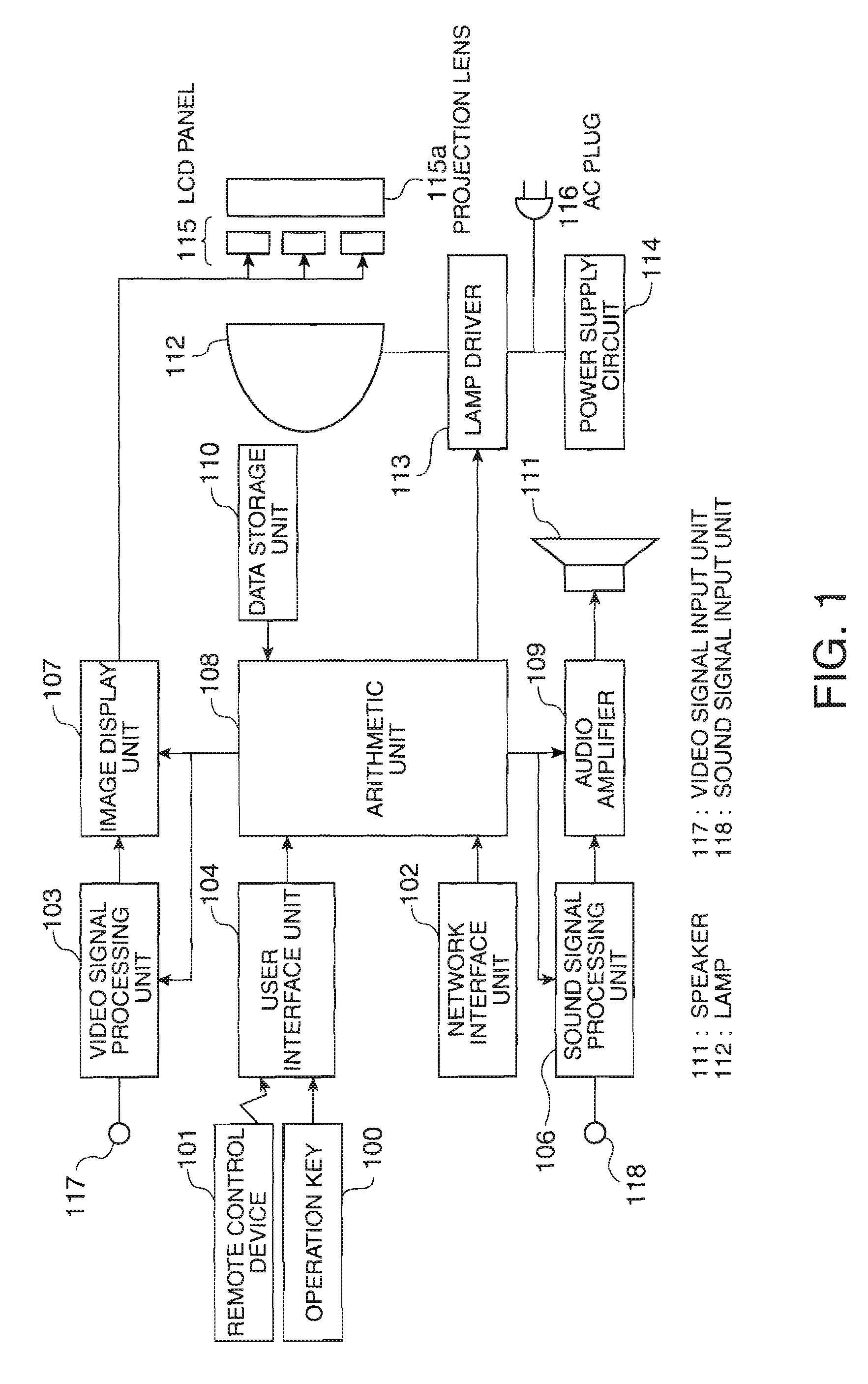
[0040]FIG. 1 is a functional block diagram of a projector as an example of an electronic apparatus according to a first embodiment of the invention.

[0041]A projector shown in FIG. 1 includes an operation key 100, a remote control device 101, a network interface unit 102, a video signal processing unit 103, a user interface unit 104 (receiving unit), a sound signal processing unit 106, an image display unit 107, an arithmetic unit 108, an audio amplifier 109, a data storage unit 110, a speaker 111, a lamp 112, a lamp driver 113, a power supply circuit 114, an LCD panel 115, a projection lens 115a, an AC plug 116, an image signal input unit 117, and a sound signal input unit 118.

[0042]Moreover, in FIG. 1, only the circuit configuration required for illustrating the projector according to the first embodiment is shown, and other circuit configurations are omitted.

[0043]The operation key 100 and the remote control device 101 are used by a user for the operation of the projector. The net...

second embodiment

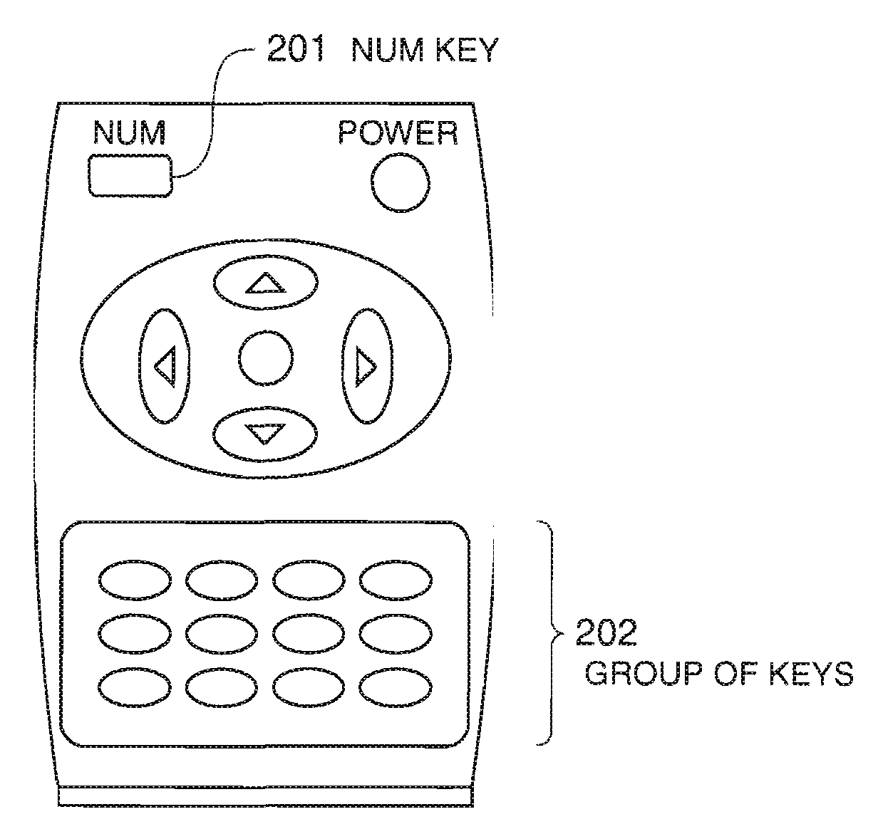
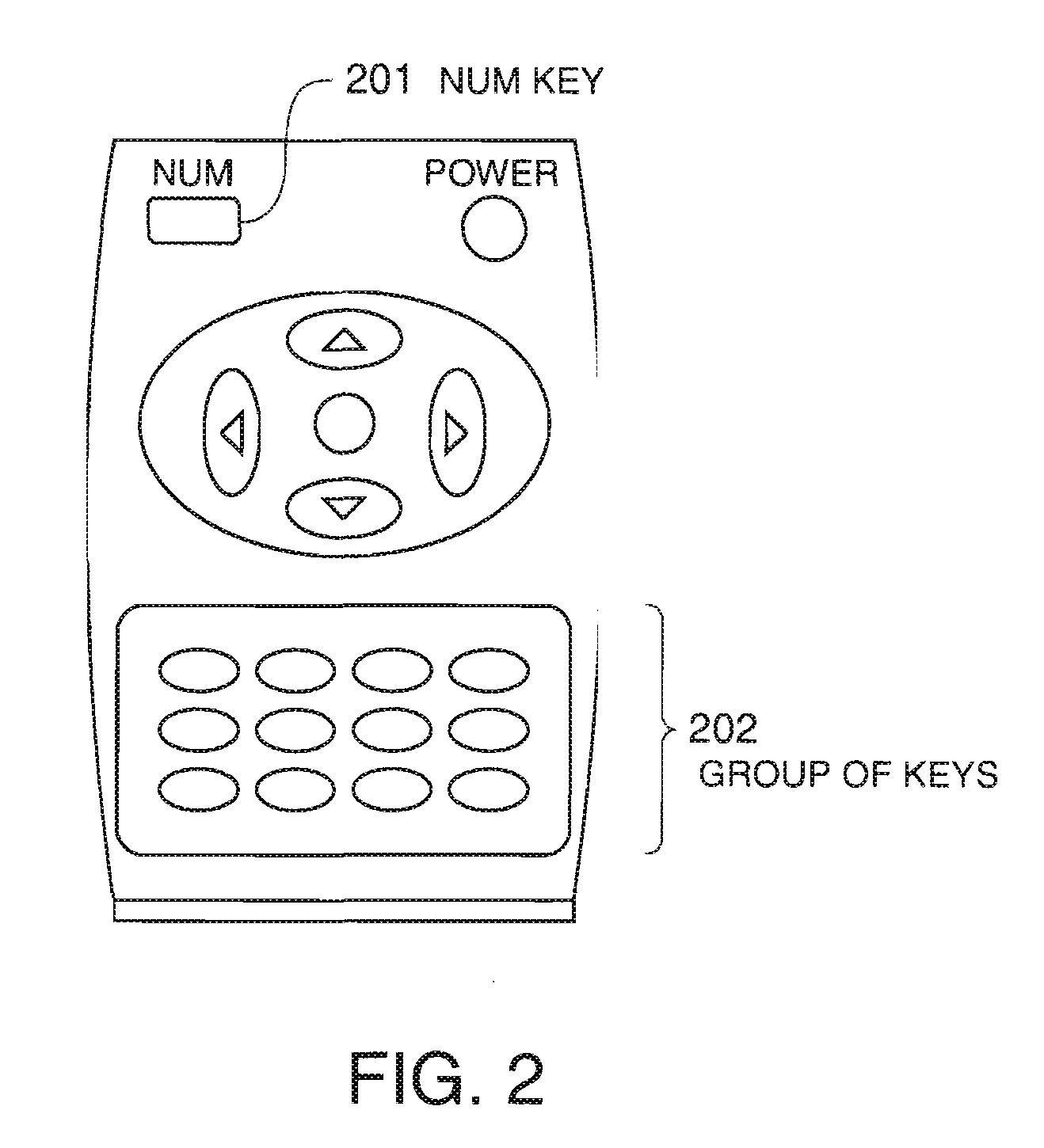
[0081]In the electronic apparatus according to the first embodiment, when the ID number set in the apparatus main body is inconsistent with ‘NUM key’ and ‘Numeric key’ to be transmitted by the remote control device, the apparatus do not respond to the operation of the remote control device.

[0082]In an electronic apparatus according to a second embodiment of the invention, the ID number of the apparatus main body is enabled for a specific setting menu.

[0083]FIG. 10 is a functional block diagram of a projector as an example of the electronic apparatus according to the second embodiment of the invention.

[0084]A data storage unit 110 stores an ID enabling setting table 119. An example of the configuration of the ID enabling setting table 119 and data will be described below with reference to FIG. 15. Other parts are the same as those in the first embodiment shown in FIG. 1, and the descriptions thereof will be omitted. Moreover, although an ID flag 120 is provided in the data storage un...

third embodiment

[0118]In the projector according to the first or second embodiment, the remote control device riot having an ID transmission function can exhibit the same effects as the remote control device having an ID transmission function.

[0119]A projector according to a third embodiment is configured such that the correspondence between an existing projector and an ID number can be established through a software update. Moreover, the configuration is the same as that in the second embodiment shown in FIG. 10, and the description thereof will be omitted.

[0120]FIG. 20 is a diagram showing an example of the use of the projector according to the third embodiment.

[0121]In general, software, which is called firmware for defining the operation of the electronic apparatus, is installed in a storage unit or the like that is incorporated into an apparatus main body. Upon version-up of such firmware, firmware may be automatically downloaded and the version-up may be performed through a request to a manuf...


PUM


Abstract

An electronic apparatus includes a remote control device that transmits a predetermined key code signal, excluding a unique key code (signal) for identifying the device itself, and an operation information signal of a user, a receiving unit that receives the signals to be transmitted by the remote control device, an arithmetic unit, and an ID number setting unit that sets an ID number peculiar to a main body. The arithmetic unit receives the operation information signal when information specified by a set of the key code received by the receiving unit and numerals is consistent with information specified by the ID number set by the ID number setting unit.

Description

BACKGROUND[0001]1. Technical Field[0002]The present invention relates to an electronic apparatus that operates by a remote control device, and a projector.[0003]2. Related Art[0004]As a technology about a remote control device transmitting an ID code, there is known a remote control device described in JP-A-2001-245371. In the remote control device, when a communication start key of a remote control device is depressed, the remote control device transmits an ID code transmission request signal to all apparatuses within a remote control signal transmission range. Then, the remote control device receives all ID codes returned by apparatuses receiving the ID code transmission request signal and selects an arbitrary apparatus among the apparatuses to set its display and operation keys required for the operation of the apparatus so as to operate the apparatus.[0005]When a plurality of electronic apparatuses operate by the remote control device, the remote control device has a function of...

Claims


Application Information

Patent Timeline
IPC IPC(8): H04B1/06G03B21/00H04N5/00H04Q9/00
CPCG03B23/00
Inventor HAYAMA, HITOSHIFUJIWARA, SHUICHI
Owner SEIKO EPSON CORP
Why Eureka
Try Eureka