D-shaped tube for header

a header and d-shaped technology, applied in the direction of engines, mechanical equipment, machines/engines, etc., can solve the problems of premature failure of the exhaust manifold assembly, high exhaust gas temperature at the manifold, and high stress on the manifold pipe, so as to reduce the turbulence of the cooling water flow, improve heat transfer, and reduce the effect of turbulen

Inactive Publication Date: 2007-09-13
COMPX INTERNATIONAL
View PDF7 Cites 7 Cited by
  • Summary
  • Abstract
  • Description
  • Claims
  • Application Information

AI Technical Summary

Benefits of technology

[0016] In accordance with aspects of certain embodiments of the present subject matter, methodologies are provided to reduce the turbulence of the cooling water flow between the exhaust pipe and jacket pipe to improve heat transfer from the exhaust gases to the cooling water.
[0017] In accordance with further certain aspects of other embodiments of the present subject matter, methodologies have been developed to improve heat transfer to the cooling water by providing shaped correspondence between the walls of the nested exhaust pipe and jacket pipe to enhance the cooling water flow characteristics.
[0018] In one present exemplary embodiment, a water cooled exhaust assembly preferably comprises an outer tube portion, an inner tube portion having a generally free end thereof, and a mounting flange for supporting such assembly relative to an associated internal combustion engine. Additionally, there is provided at least one cooling water entrance port formed in the mounting flange, and at least one cooling water exit port formed in the outer tube portion. In such preferred exemplary embodiment, preferably the inner and outer tube portions are configured for the inner tube portion to pass exhaust gases from an associated internal combustion engine while a space is formed between the inner and outer tube portions for defining a cooling water channeling system in conjunction with the entrance and exit ports. Still further in such exemplary embodiment, preferably the inner and outer tube portions have predetermined shaped correspondence between the walls thereof, for reducing turbulence of the flow characteristics of cooling water passing therethrough, for improved heat transfer characteristics.

Problems solved by technology

While high temperature of the exhaust gases is desirable for high power output from the engine, high exhaust gas temperatures at the manifold place a high degree of stress on the manifold pipes.
Moreover, under some conditions, hot combustion gases coming from an internal combustion engine may be combustible and potentially explosive.
Excessively high temperatures can lead to premature failure of exhaust manifold assemblies, compromising the ability of the exhaust manifold assembly to remove the heat and exhaust gases from the engine and engine compartment.
Thus, relying on more sophisticated and possibly more expensive materials to handle the hot exhaust gases is not a preferred solution.
However the water flow is limited, a predetermined minimum flow of cooling water is maintained through the exhaust system, at least either at periodic intervals, or at a constant but lowered rate, to maintain cooling in the exhaust system on rubber components of the exhaust system.
While various implementations of a water cooled exhaust system exist, no design has emerged that generally encompasses all of the desired characteristics as hereafter presented in accordance with the subject technology.

Method used


Image

  • D-shaped tube for header
  • D-shaped tube for header
  • D-shaped tube for header

Examples


Embodiment Construction

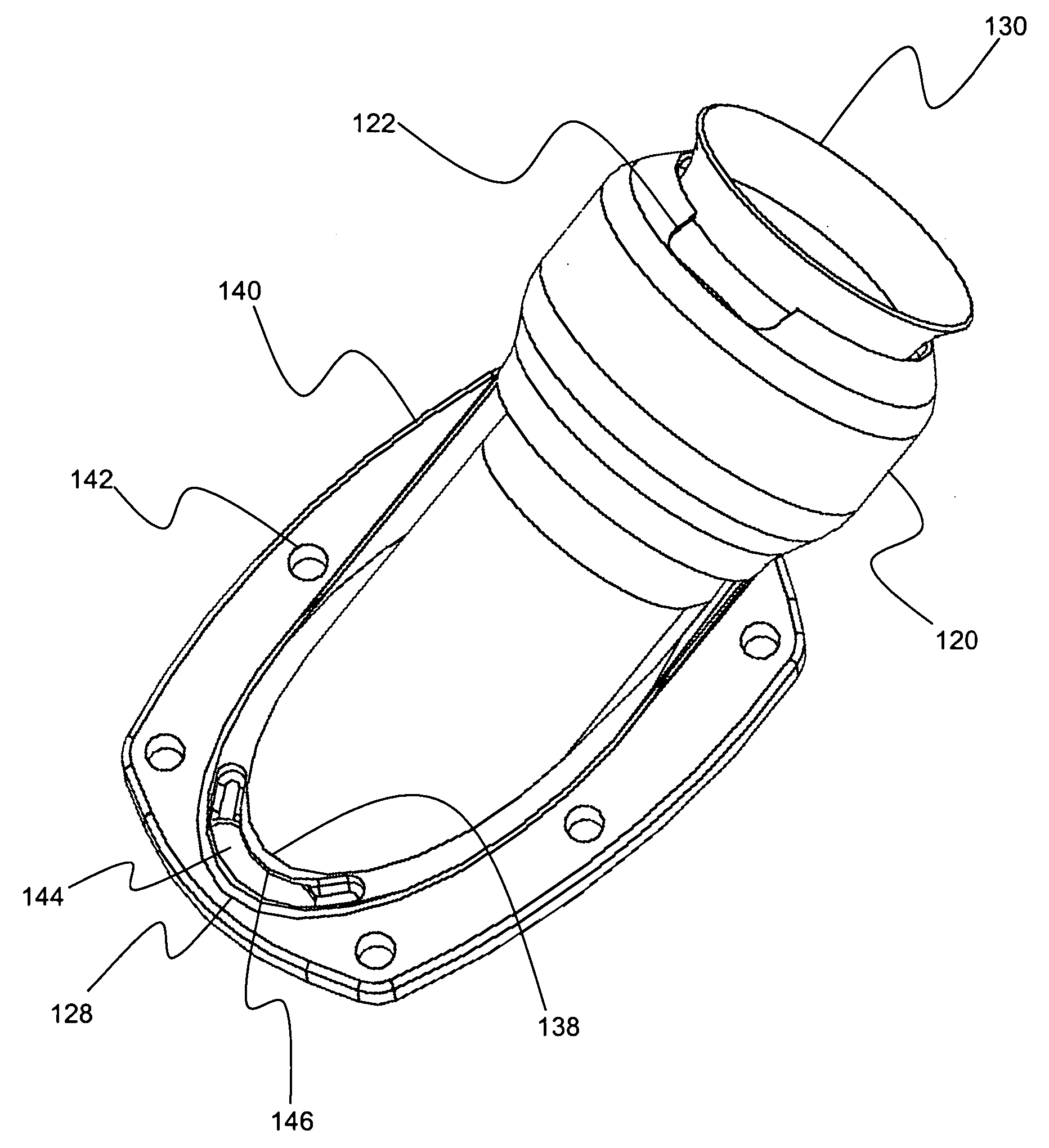
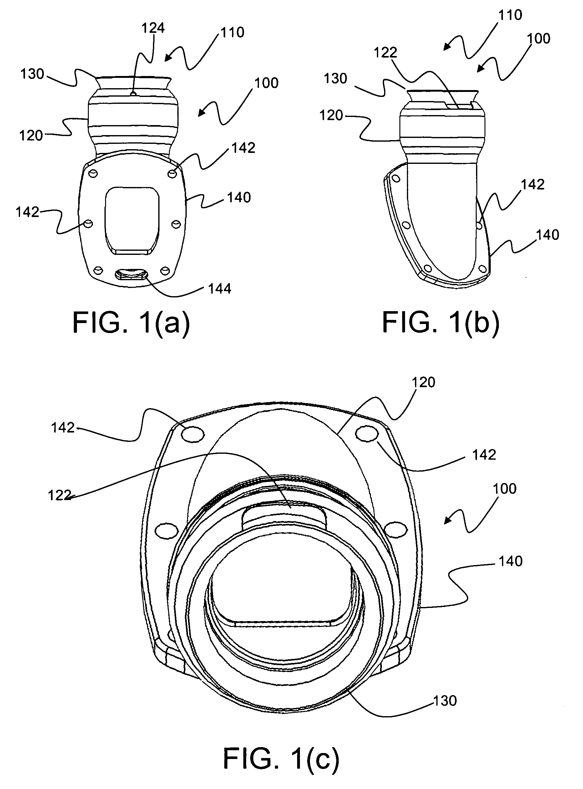
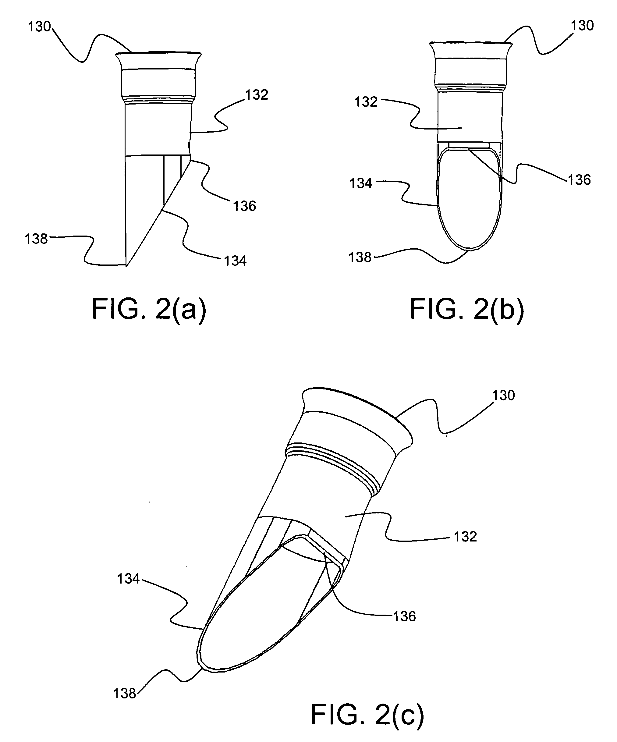
[0033] As discussed in the Summary of the Invention section, the present subject matter is particularly concerned with improved arrangements and methodology for providing water cooling for exhaust systems for internal combustion engines.

[0034] Selected combinations of aspects of the disclosed technology correspond to a plurality of different embodiments of the present subject matter. It should be noted that each of the exemplary embodiments presented and discussed herein should not insinuate limitations of the present subject matter. Features or steps illustrated or described as part of one embodiment may be used in combination with aspects of another embodiment to yield yet further embodiments. Additionally, certain features may be interchanged with similar devices or features not expressly mentioned which perform the same or similar functions.

[0035] Reference will now be made in detail to the presently preferred embodiments of the subject water cooled exhaust system. Referring n...


PUM


Abstract

Disclosed is a water cooled exhaust assembly for use in association with an internal combustion engine in a marine environment. Inner and outer nested tubes are affixed to a mounting flange to form, in conjunction with an access port in the mounting flange, a cooling water flow channel to provide cooling of exhaust gases from the engine. The inner tube is formed with a flattened portion to produce a reduction in exhaust gas turbulence in the flow channel with a consequent increase in heat transfer capability.

Description

PRIORITY CLAIM [0001] This application claims the benefit of previously filed U.S. Provisional Patent Application entitled “D-SHAPED TUBE FOR HEADER,” assigned U.S. Ser. No. 60 / 721,762, filed Sep. 29, 2005, and which is incorporated herein by reference for all purposes.FIELD OF THE INVENTION [0002] The present subject matter relates to exhaust systems and, more particularly, to water cooled exhaust systems for marine applications. BACKGROUND OF THE INVENTION [0003] The incorporation of water cooling for exhaust systems for internal combustion engines has many advantages. While high temperature of the exhaust gases is desirable for high power output from the engine, high exhaust gas temperatures at the manifold place a high degree of stress on the manifold pipes. Moreover, under some conditions, hot combustion gases coming from an internal combustion engine may be combustible and potentially explosive. Thus, excess heat from the hot combustion gases must be continuously removed in or...

Claims


Application Information

Patent Timeline
Patent Type & Authority Applications(United States)
IPC IPC(8): F01N5/02F01N3/02F01N13/08
CPCF01N13/082F01N13/004
Inventor ZELINSKI, JOSEPH R.
Owner COMPX INTERNATIONAL
Why Eureka
Try Eureka