Run-flat tire

Inactive Publication Date: 2007-09-13
TOYO TIRE & RUBBER CO LTD
View PDF0 Cites 3 Cited by
  • Summary
  • Abstract
  • Description
  • Claims
  • Application Information

AI Technical Summary

Benefits of technology

[0017] In accordance with the structure mentioned above, since the annular protrusion section reinforced by the second bead can hold the rim flange at a time of the run-flat traveling, an installation stability to the rim is increased, and it is possible to achieve an excellent rim disengagement resistance. Further, in accordance with the run-flat tire of the present invention, since the first soft rubber layer having the corner section tapered toward the tire inner peripheral side is arranged in the protrusion section having the inner diameter smaller than the outer diameter of the rim flange, the protrusion section tends to be bent to the inner side in the tire width direction and the rim assembling property can be improved. In other words, in the rim assembly of the tire, it is easy to execute a work of installing the bead section dropped in the rim drop onto the rim base and thereafter pulling up the annular protrusion section to the outer side so as to get over the rim flange. Accordingly, in the double bead type run-flat tire, it is possible to effectively achieve both of the rim disengagement resistance and the rim assembling property. In this case, the specified rim indicates the rim forming the standard determined by JATMA in correspondence to the tire size, and the specified rim installing time indicates a state of being installed to the specified rim at an air pressure of 180 kPa. Further, the first soft rubber layer means a softer rubber layer than the other rubber layers arranged in the protrusion section.
[0034] Since the annular protrusion section reinforced by the second bead and the fiber layer is pressed to the outer peripheral side curved surface of the rim flange at the run-flat traveling time, by arranging the fiber layer between the second bead and the second soft rubber layer, it is possible to effectively increase the fitting force to the rim, and it is possible to achieve the more excellent rim disengagement resistance.

Problems solved by technology

However, since a pressure application to a rim of a bead section is weakened and a fitting force is lowered in a state in which the air pressure in the inner section of the tire is lowered (in a run-flat state), there is a problem that the rim tends to be detached from the bead section.
However, in the run-flat tire mentioned above, it has been known that the rim disengagement resistance is not sufficient.
Accordingly, there is a problem that a bead section 1o positioned in an outer side of the vehicle tends to get over a hump of the rim 8 so as to disengage to an inner side.
However, in the conventional double bead type run-flat tire, it is hard to assemble the rim.
As mentioned above, since the annular protrusion section has the inner diameter smaller than the outer diameter of the rim flange, and is reinforced by the second bead, it is very hard to execute an operation.
In other words, in the conventional double bead type run-flat tire, since the annular protrusion section provided for securing the rim disengagement resistance deteriorates a rim assembling property, it is hard to achieve both of the rim disengagement resistance and the rim assembling property.
Further, in the conventional double bead type run-flat tire, there is a case that the rim disengagement resistance is not sufficient, and the conventional double bead type run-flat tire can not respond to a demand of intending to securely prevent the rim disengagement.
In conventional, in order to improve the rim disengagement resistance, there have been employed a means for increasing a volume of the reinforcing rubber layer or increasing a tread rigidity, however, there has been a problem that a deterioration of ride comfort performance and an increase of a tire weight are caused.
In this case, the run-flat tire described in the following patent document 5 is structured such that a rim displacement preventing layer is provided in the bead reinforcing section for the purpose of increasing a traveling performance in the run-flat state, however, the patent document 5 does not disclose a structure which can solve the problem of the rim disengagement resistance as mentioned below.

Method used


Image

  • Run-flat tire
  • Run-flat tire
  • Run-flat tire

Examples


first embodiment

OTHER ASPECT OF FIRST EMBODIMENT

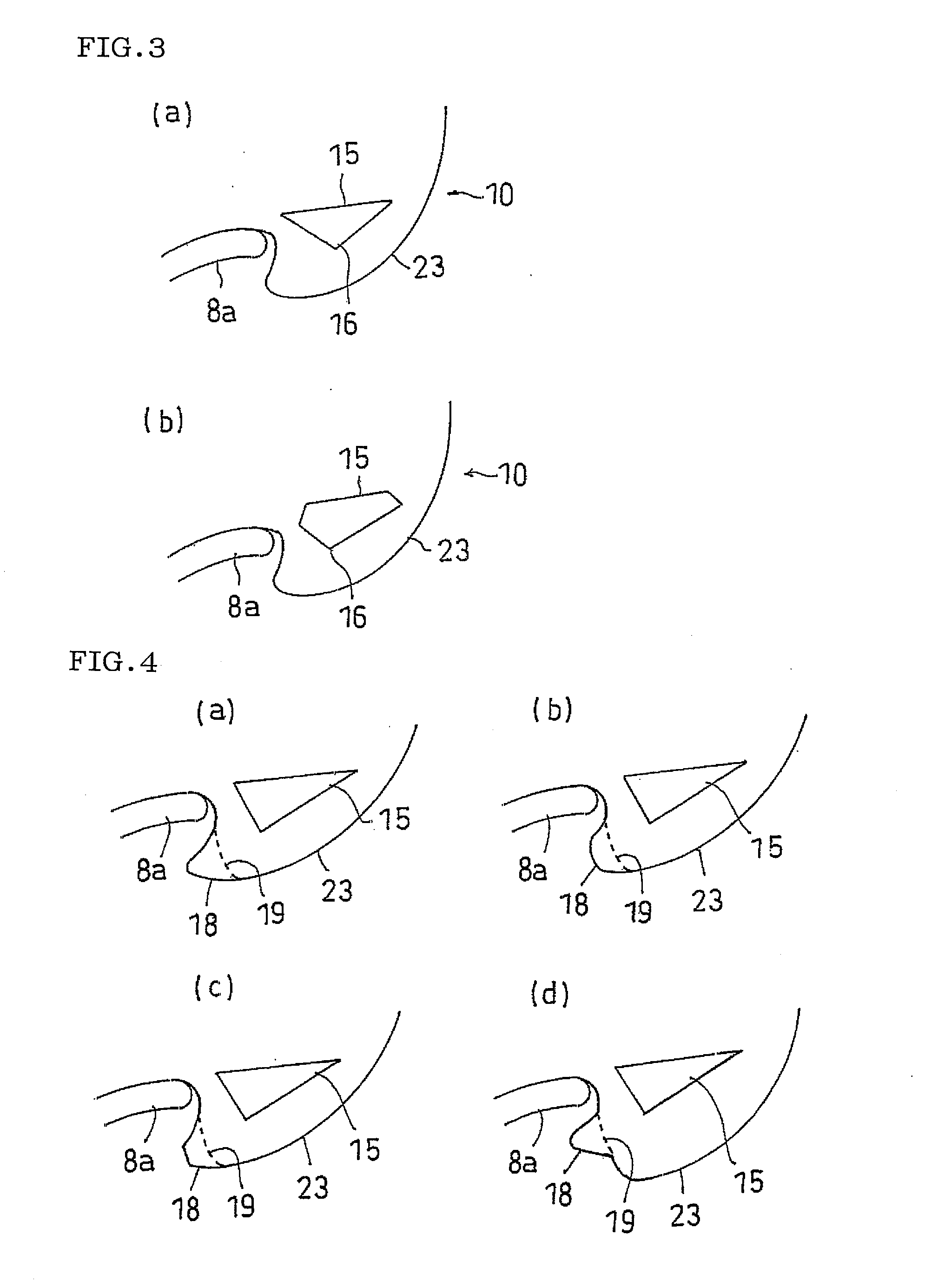
[0082] (1) The soft rubber layer 15 provided in the run-flat tire in accordance with the present invention can be formed in various cross sectional shapes so as to be provided in the ridge section 23 as far as the soft rubber layer 15 has the corner section 16 tapered toward the tire inner peripheral side. For example, the soft rubber layer 15 shown in FIG. 3(a) is formed in an isosceles triangular shape in which lengths of both sides of the corner section 16 are equal. Further, the soft rubber layer 15 shown in FIG. 3(b) is formed in a pentagonal sectional shape. In the case that the soft rubber layer 15 is formed in the other cross sectional shapes than the triangular shape, it is preferable that a bisector of the corner section 16 tapered toward the tire inner peripheral side is inclined to the inner side in the tire width direction toward the tire inner peripheral side. In this case, a chamfer or a roundness may be applied to the corner section 16...

example of first embodiment

[0086] An example tire which concretely shows the structure and effect of the present invention will be explained.

(1) Rim Disengagement Resistance

[0087] Each of test tires installed to a rim having a wheel size of 18×8JJ is attached to a left front side of an actual car (domestically built 3000 cc class FR car), and there is executed a so-called J-turn travel of turning on a circular course having a radius of 20 m in a clockwise direction from a straight traveling. Each of the test tires is set to a run flat state having an internal pressure of 0 kPa, and a rim disengagement resistance is evaluated on the basis of a traveling speed (which is in proportion to a lateral G) at a time when the rim disengagement is generated. The traveling speed starts from 25 km / h, and the travel is executed until the rim disengagement is generated in accordance with a method of 5 km / h increment. An evaluation is executed by an index number in which the conventional example 1 is set to 100. The large...

example 1

CONVENTIONAL EXAMPLE 1

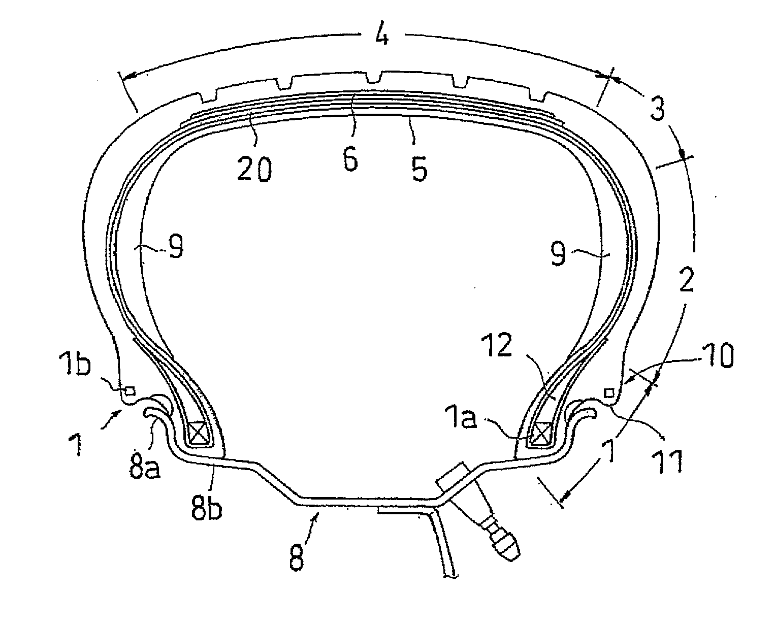
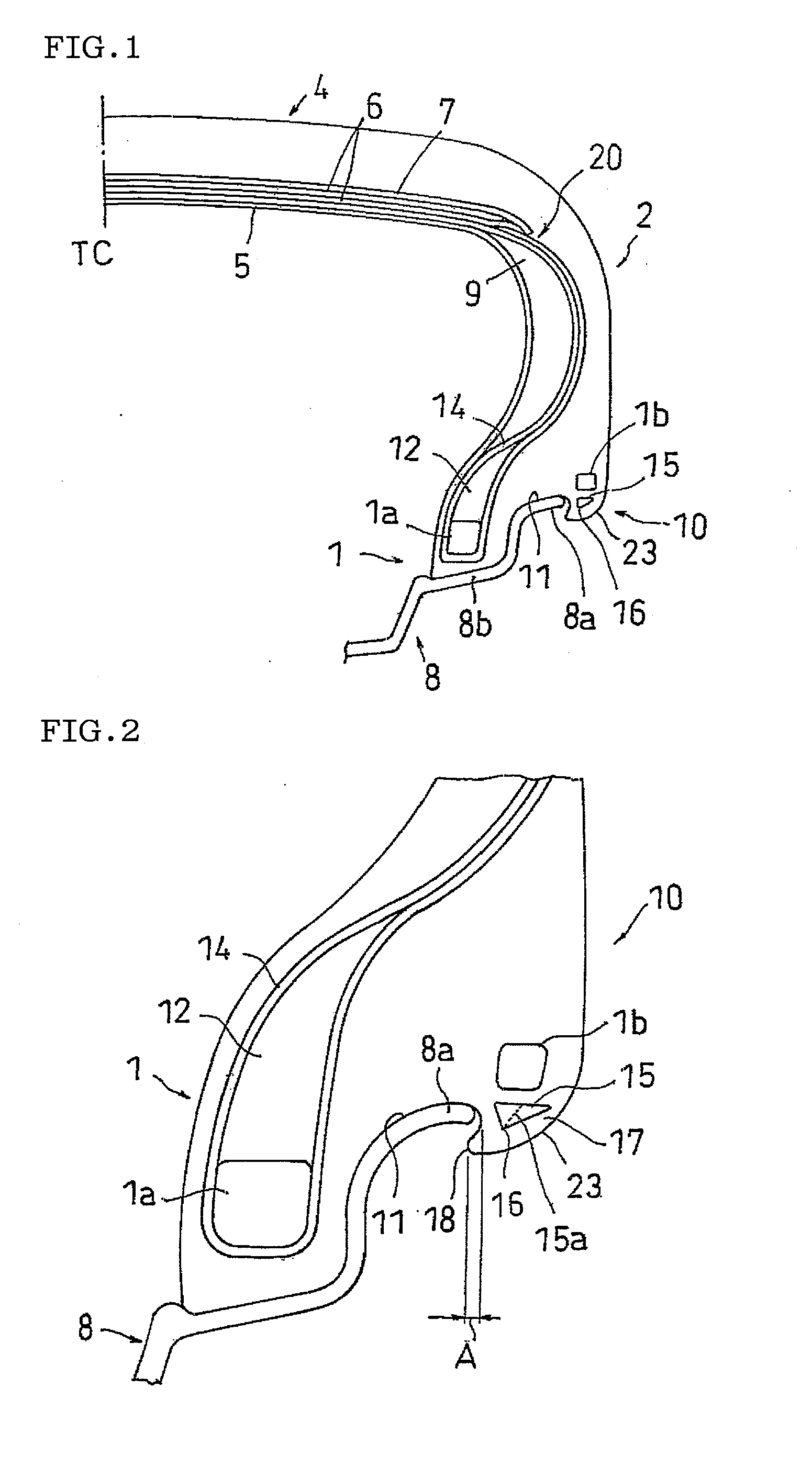
[0089] In the run-flat tire shown in FIGS. 1 and 2, a conventional double bead type run-flat tire (tire size 245 / 40ZR18) is manufactured so as to be provided with no soft rubber layer 15 and no projection section 18, and is set to a conventional example 1.


PUM


Abstract

The present invention provides a run-flat tire provided with a reinforcing rubber layer 9 arranged in a side wall section 2 so as to be formed in a crescent cross sectional shape, an annular protrusion section 10 protruding to an outer side in a tire width direction from at least one of bead sections 1, and having an inner peripheral side surface 11 facing to an outer peripheral side curved surface of a rim flange 8a at a time of installing a specified rim, and an annular bead 1b arranged in the annular protrusion section 10, in which the run-flat tire is provided with a ridge section 23 connecting to an outer side in the tire width direction from an inner peripheral side surface 11 of the annular protrusion section 10 so as to protrude to an inner peripheral side of the tire, and having an inner diameter smaller than an outer diameter of the rim flange 8a, and a soft rubber layer 15 arranged in the ridge section 23 and having a corner section 16 tapered toward the tire inner peripheral side.

Description

TECHNICAL FIELD [0001] The present invention relates to a so-called double bead type run flat tire provided with a reinforcing rubber layer arranged in a side wall section, an annular protrusion section protruding to an outer side in a tire width direction of a bead section, and a bead arranged in the annular protrusion section. BACKGROUND ART [0002] Conventionally, there has been known a so-called side reinforcing type run-flat tire provided with a reinforcing rubber layer in a side wall section. In accordance with the run-flat tire mentioned above, the reinforcing rubber layer supports a tire so as to suppress a flattening at a time when an air pressure in an inner section of the tire is lowered due to a puncture or the like, whereby a run-flat traveling can be executed. However, since a pressure application to a rim of a bead section is weakened and a fitting force is lowered in a state in which the air pressure in the inner section of the tire is lowered (in a run-flat state), t...

Claims


Application Information

Patent Timeline
IPC IPC(8): B60C17/04
CPCB60C13/04B60C15/024B60C15/06Y10T152/10819B60C17/0009Y10T152/10846B60C13/009
Inventor SEGAWA, MASAHIROKAWAMURA, KAZUHIKOKODAMA, JUNKANAI, MASAYUKI
Owner TOYO TIRE & RUBBER CO LTD
Why Eureka
Try Eureka