Force sensor and manufacturing method for a force sensor

Inactive Publication Date: 2007-09-13
BOSCH REXROTH AG
View PDF17 Cites 17 Cited by
  • Summary
  • Abstract
  • Description
  • Claims
  • Application Information

AI Technical Summary

Problems solved by technology

Such a usual force sensor may operate reliably, but

Method used


Image

  • Force sensor and manufacturing method for a force sensor
  • Force sensor and manufacturing method for a force sensor
  • Force sensor and manufacturing method for a force sensor

Examples


Embodiment Construction

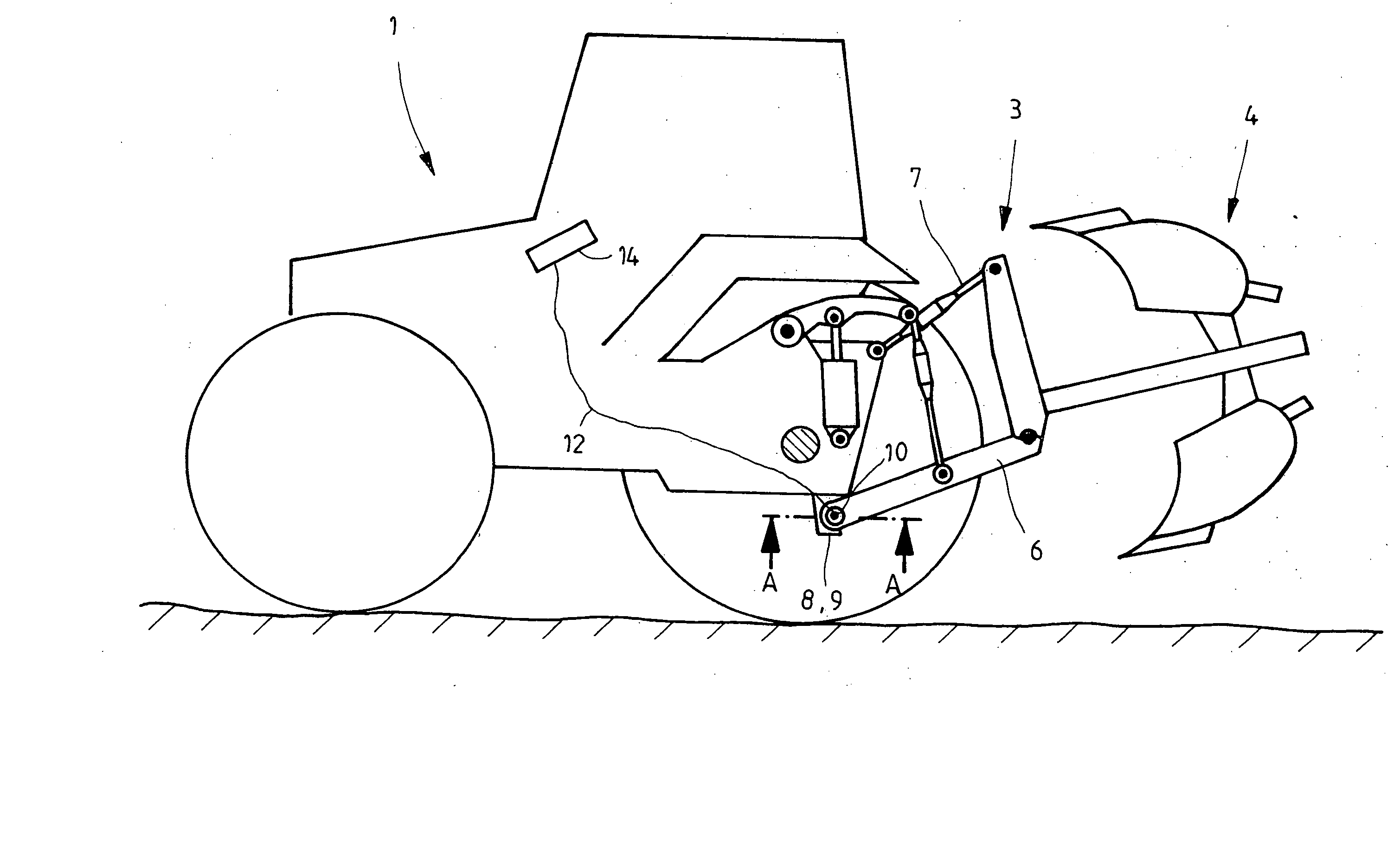
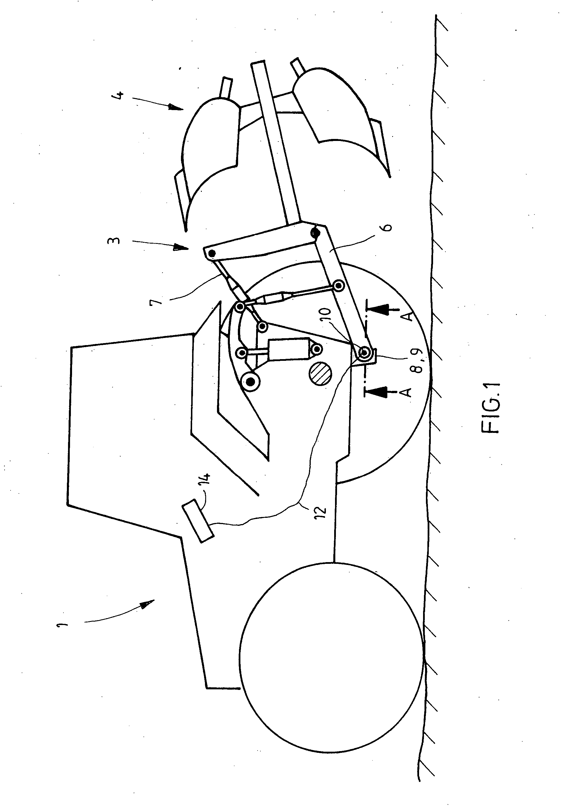
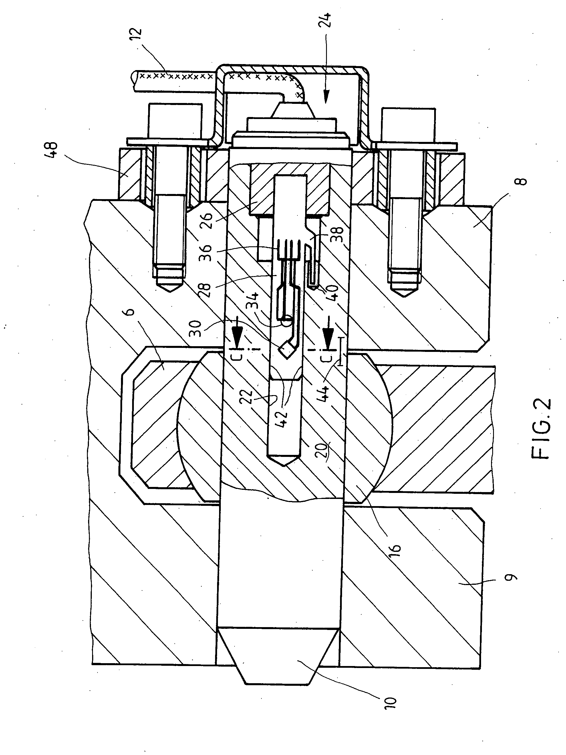
[0034] In a schematic representation, FIG. 1 shows a tractor 1, at whose rear end a hoisting gear 3 having a plow 4 is held. Hoisting gear 3 is supported via various linkages on the rear end of tractor 1. Of these linkages, one lower linkage 6 and one upper linkage 7 are shown in FIG. 1. Lower linkage 6 is held at two fastening arms 8, 9 of tractor 1. On lower linkage 6, an attachment such as plow 4 is held. Lower linkage 6 is fastened by a joint bolt 10 to fastening arms 8 and 9. Joint bolt 10 is provided with a force measurement device, by which a shear force or a tensile force on lower linkage 6 is recorded. Joint bolts 10 having an integrated force measurement device are also designated as force measurement bolts. A signal corresponding to a measured force is transmitted to a control unit 14 via a signal line 12. Control unit 14 controls, for example, hoisting gear 3, in order to regulate the depth of penetration of plow 4.

[0035] The region in which lower linkage 6 is fastened ...


PUM


Abstract

A force sensor has a cylindrically shaped housing which is elastically deformable by a force acting on it perpendicularly to its center axis. The housing has a hollow space. A measuring transducer device is situated in the hollow space, by which the deformation of the housing is able to be recorded. The measuring transducer device has a plate-shaped support plate on whose surface an expansion measurement transducer is fastened. The support plate is fastened in the hollow space in such a way that a deformation of the housing is transferred to the support plate.

Description

RELATED APPLICATION INFORMATION [0001] The present application claims priority to German Patent Application No. 10 2006 007 385.1, which was filed on Feb. 17, 2006 in the German Patent Office, and the contents of which are hereby incorporated by reference. FIELD OF THE INVENTION [0002] The present invention relates to a force sensor. BACKGROUND INFORMATION [0003] A force sensor is used, for instance, in tractors. There it is used as a joint bolt for fastening the lower linkage on the tractor and measures tensile force or shear force acting on the lower linkage. Other fields of application are, for instance, load measurement in hay balers or stacker trucks. Such a usual force measurement bolt is discussed in German Patent document no. DE 30 04 952 A1. The force measurement bolt has a housing shaped like a hollow cylinder. A magnetic measuring transducer is set into the end face of the housing opening, and it records a mechanical load of the housing. The magnetic measuring transducer ...

Claims


Application Information

Patent Timeline
IPC IPC(8): B62B15/00
CPCG01L1/005G01L5/136G01L1/2237
Inventor STEPRATH, WERNERDREYLING, JUDITHTHIERBACH, PETERBARTELS, OLAF
Owner BOSCH REXROTH AG
Why Eureka
Try Eureka