Vehicle brake control device

a brake control and vehicle technology, applied in the direction of brake systems, brake components, transportation and packaging, etc., can solve the problems of w/c pressure change, driver experience a bad brake feeling, etc., and achieve the effect of improving the brake feeling

Inactive Publication Date: 2007-09-13
ADVICS CO LTD
View PDF7 Cites 24 Cited by
  • Summary
  • Abstract
  • Description
  • Claims
  • Application Information

AI Technical Summary

Benefits of technology

[0006]It is therefore an object of the present invention to provide a vehicle brake control device which adjusts W / C pressures by using linear valves and still makes a driver experience an improved brake feeling.

Problems solved by technology

In this case, however, the W / C pressure changes so sensitively to the operation to the brake pedal that it changes even when the driver is not intentionally operating the brake pedal.
This causes the driver to experience a bad brake feeling.

Method used


Image

  • Vehicle brake control device
  • Vehicle brake control device
  • Vehicle brake control device

Examples


first embodiment

[0039]The vehicle brake control device according to a first embodiment of the present invention is applied to a vehicle with an X-shaped hydraulic circuit including two conduit systems, one of which serves the right front wheel and the left rear wheel and the other of which serves the left front wheel and the right rear wheel.

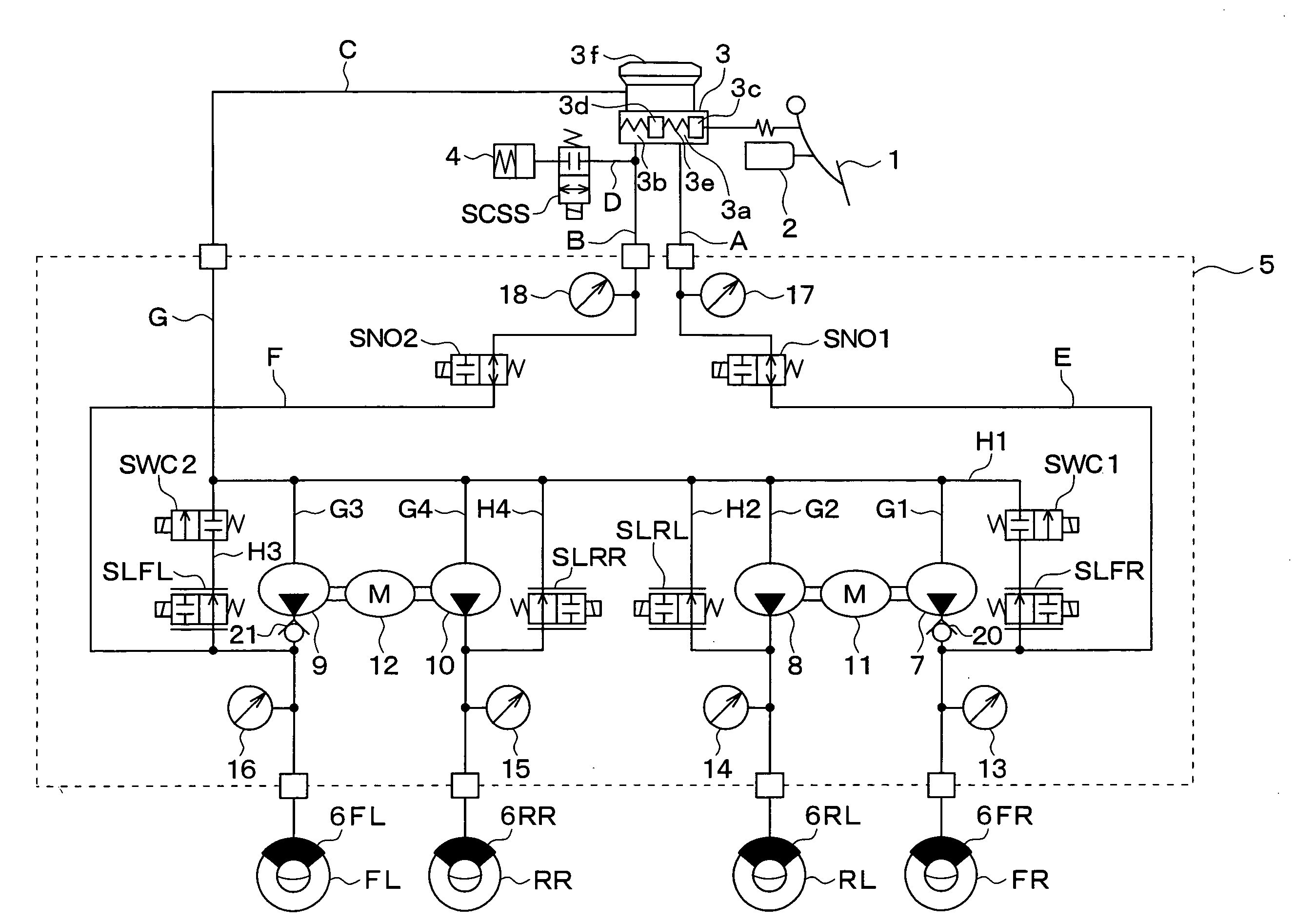
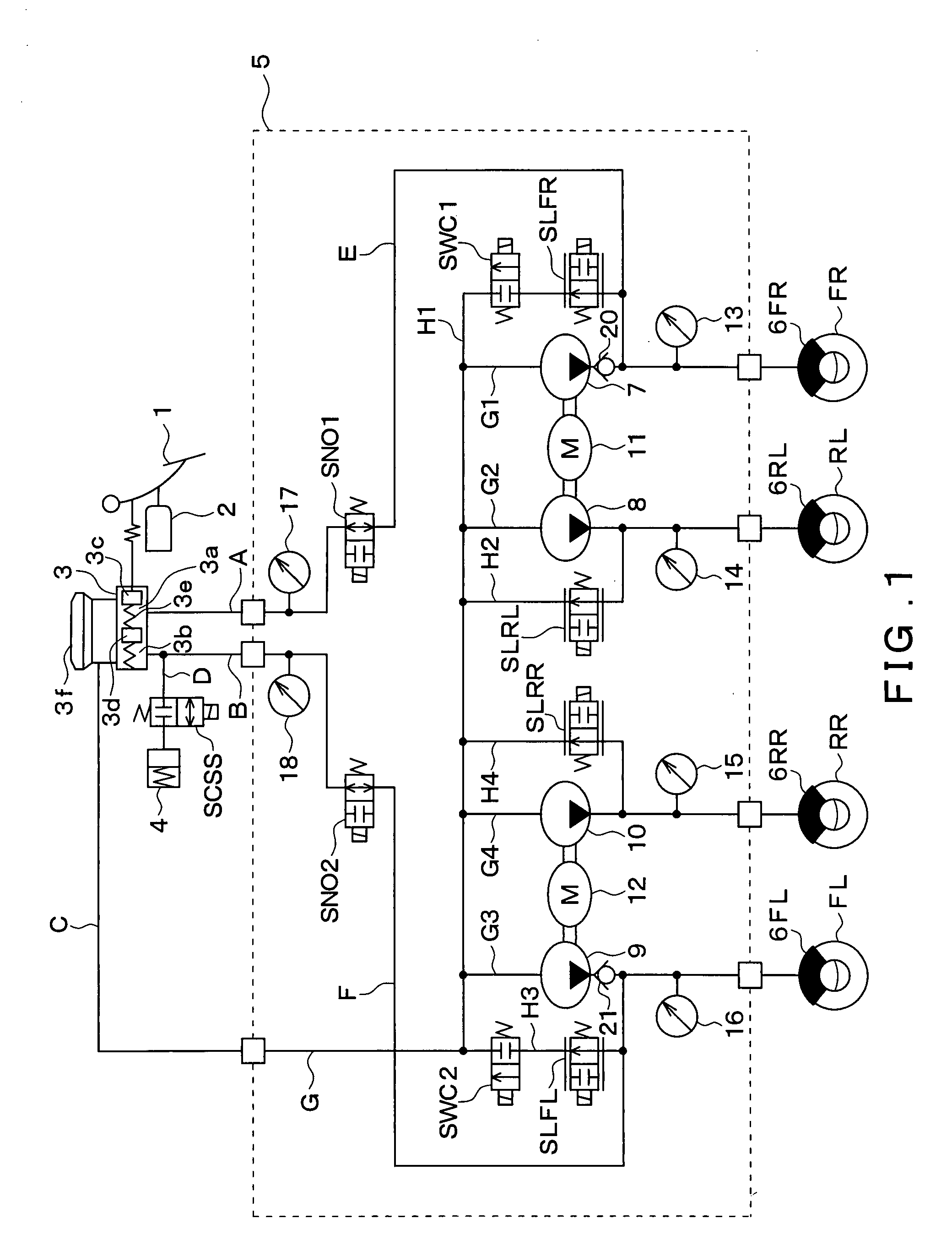
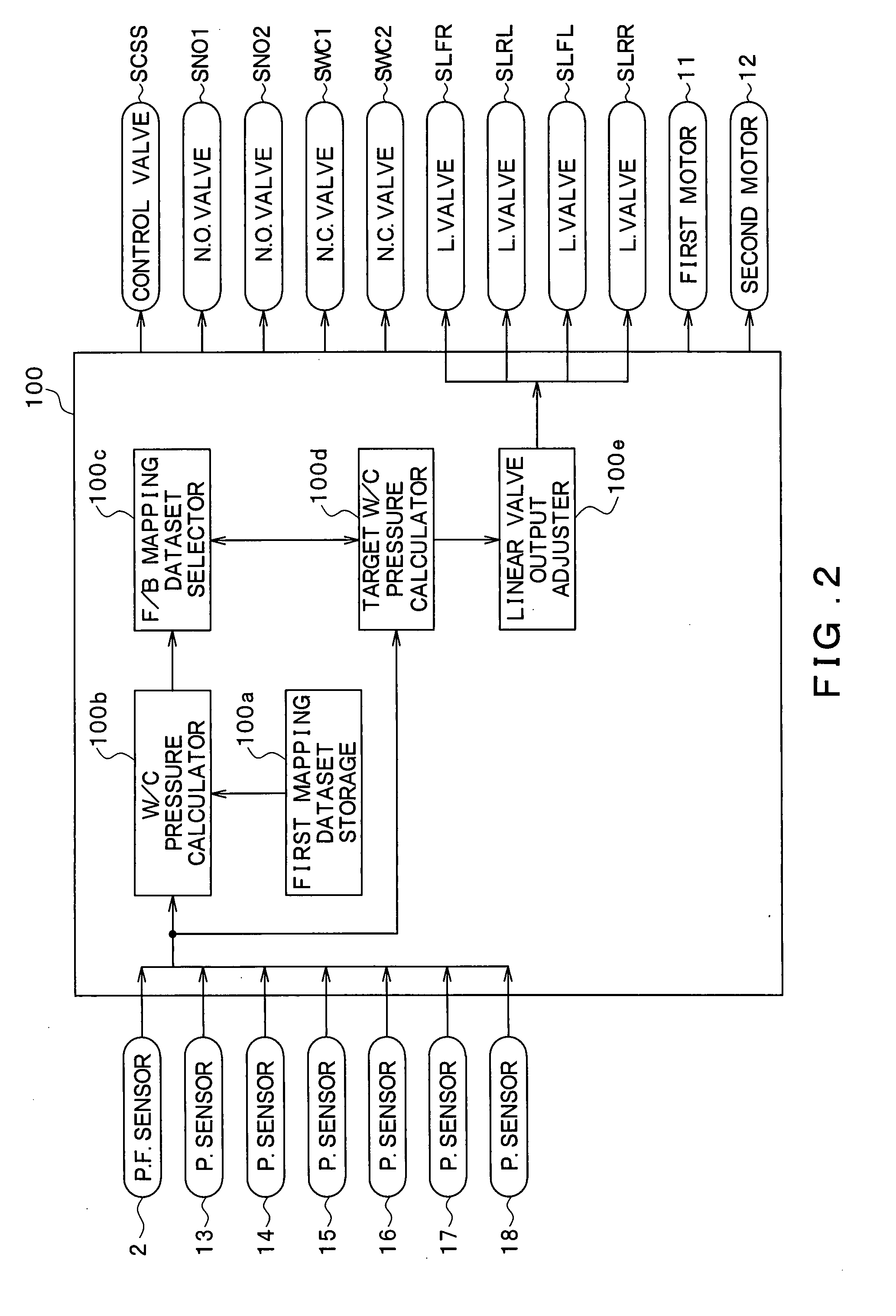
[0040]As shown in FIG. 1, the vehicle brake control device includes a brake pedal 1, a depression force sensor 2, a master cylinder (hereinafter referred to as an M / C) 3, a stroke control valve SCSS, a stroke simulator 4, a brake fluid pressure control actuator 5, and wheel cylinders (hereinafter referred to as W / Cs) 6FL, 6FR, 6RL, 6RR, as well as a brake ECU 100 shown in FIG. 2.

[0041]When the brake pedal 1, which is an example of a brake operating member, is depressed by a driver, the depression force applied to the brake pedal 1 is inputted to the depression force sensor 2, and a detection signal corresponding to the applied depression force is outputted by t...

second embodiment

[0104]Hereinafter, a second embodiment of the present invention will be described. The present embodiment differs from the first embodiment in that the current-values to be supplied to the first to fourth linear valves SLFR to SLRR are determined so that they reflect a mechanical relation between the currents to the first to fourth linear valves SLFR to SLRR and the differential pressures generated at the first to fourth linear valves SLFR to SLRR.

[0105]The differential pressures generated at the first to fourth linear valves SLFR to SLRR change depending on the current values of the current to the first to fourth linear valves SLFR to SLRR, respectively. Therefore, the current values for the first to fourth linear valves SLFR to SLRR are adjusted in order to generate the differential pressures which correspond to determined target W / C pressures. More specifically, the target W / C pressures are identical with the differential pressures. The mechanical relation between the current val...

third embodiment

[0119]Hereinafter, a third embodiment of the present invention will be described. In the second embodiment, the current value for the first to fourth linear valves SLFR to SLRR is properly adjusted in accordance with increase or decrease of the target W / C pressure. However, when the current value changes quickly by a large amount such as from the current value I1 to the current value I2 shown in FIG. 6, the driver may experience an uncomfortable feeling that the generated W / C pressure jumps up or down quickly. The vehicle brake control device of the present embodiment is aimed for preventing the uncomfortable feeling from occurring. The vehicle brake control device of the present embodiment differs from that of the second embodiment in the process executed by the adjusting portion 100e. The difference of the present embodiment from the second embodiment will be described in detail.

[0120]The brake ECU 100 of the present embodiment differs from that of the second embodiment in that th...


PUM


Abstract

In a vehicle brake control device, a target W/C pressure depending on an amount of operation performed to a brake operating member, exhibits hysteresis due to a forward mapping dataset and a backward mapping dataset. The vehicle brake control device selects the forward mapping dataset or the backward mapping dataset based on the amount of operation performed to the brake operating member, and determines a current value of a current to be supplied to one of first to fourth linear valves. Therefore, it is possible to prevent a wheel cylinder pressure from changing too sensitively to the operation to the brake operating member and from changing even when the driver is not intentionally operating the brake operating member. This makes the driver experience an improved brake feeling.

Description

CROSS REFERENCE TO RELATED APPLICATION[0001]This application is based on and incorporates herein by reference Japanese patent application No. 2006-54751 filed on Mar. 1, 2006.FIELD OF THE INVENTION[0002]The present invention relates to a vehicle brake control device which generates pressures (hereinafter referred to as W / C pressures) in wheel cylinders (hereinafter referred to as W / Cs) by causing pumps to apply pressures.BACKGROUND OF THE INVENTION[0003]In Japanese Patent Publication No. H10-203338, a brake-by-wire vehicle brake control device is proposed which has four pumps respectively for the four wheels of a vehicle. Two of the four pumps are located in a common conduit system for two of the four wheels and are driven by a common motor. The other two of the four pumps are located in another common conduit system for the other two of the four wheels and are driven by another common motor.[0004]The inventor of the present invention gave consideration to the vehicle brake control ...

Claims


Application Information

Patent Timeline
Patent Type & Authority Applications(United States)
IPC IPC(8): B60T13/18
CPCB60T8/4081B60T2270/402B60T13/18
Inventor NIINO, HIROAKISATO, TAKASHI
Owner ADVICS CO LTD
Why Eureka
Try Eureka