Method for controlling the automatic switching of the projector of a vehicle

a technology for projectors and vehicles, applied in the direction of point-like light sources, lighting and heating equipment, transportation and packaging, etc., can solve the problems of difficult to be sure that the light source is present in the landscape, projectors will be switched, and unnecessarily restrict the view of the driver of the vehicle, so as to increase the reliability of discrimination and increase the reliability of differentiation

Inactive Publication Date: 2007-09-13
VALEO VISION SA
View PDF9 Cites 15 Cited by
  • Summary
  • Abstract
  • Description
  • Claims
  • Application Information

AI Technical Summary

Benefits of technology

[0031] To increase the reliability of the discrimination by type of light sources, it is preferable that the acquisition a—, extraction b— and discrimination c— steps at least are repeated a plurality of times, and the results thereof compared before initiating, in the event of sufficient coincidence, switching-controlling step e—.
[0032] Advantageously, the method according to the invention also includes a step g / h—for monitoring with respect to time in order to identify the trajectories of the zones corresponding to light sources. This step, by monitoring the trajectory of a source in a sequence of images, allows the behavior of this trajectory to be compared with typical behaviors, such as a vehicle overtaking-type trajectory, of the type of the trajectory of a vehicle passing in the lane in the opposing direction, and the identification of the light sources to be made even more reliable.
[0033] In parallel with the trajectory identification step, there can also be provided a delay means for increasing the reliability of the differentiation between motorcycle lights or projectors and road signs: if the zone corresponding to a light source remains within the image, does not “leave the scene” within a given period of time, it is confirmed that it is indeed a motorcycle light and not a road sign. This waiting time for checking the displacement or non-displacement of the zone within the image can be associated with the identification of trajectories: provided that a specific trajectory has not been determined, the control of the projectors can be delayed and if, at the end of a given time, the speed of the vehicle being known, the source remains within the image, the high beam / dipped switching can be commanded.

Problems solved by technology

However, it is difficult to be sure that light sources present in the landscape originate from passing vehicle projectors or from signal lights from vehicles located on the same lane and that they are not merely reflections of the light from the projectors of the driver's own vehicle or other vehicles on road signs.
In the event of confusion, there is a risk that the projectors will be switched in a badly timed manner from the high beam mode to the dipped mode, and this will unnecessarily restrict the view of the driver of the vehicle.
There is also a risk of switching the projector from the high beam mode or dipped mode too late, owing to a detection error, and this will dazzle the driver of the passing vehicle.
Strategies based on trajectory analysis allow identification with an acceptable level of confidence of parasitic light sources such as urban lighting and, to a lesser degree, the vehicles passing the vehicle in question, but such strategies can prove ambiguous.
Although the spectral information is useful, this method requires color sensors which are not without drawbacks.
They are, in particular, equipped with filters which are liable to age prematurely.
They are also less sensitive to grey levels then black and white sensors, and this is also detrimental if these sensors are intended to be used to perform a plurality of functions, in particular for not only a dipped / high beam switching function but also a night vision function and / or an LDWS (lane departure warning signal) function.

Method used


Image

  • Method for controlling the automatic switching of the projector of a vehicle
  • Method for controlling the automatic switching of the projector of a vehicle
  • Method for controlling the automatic switching of the projector of a vehicle

Examples


Embodiment Construction

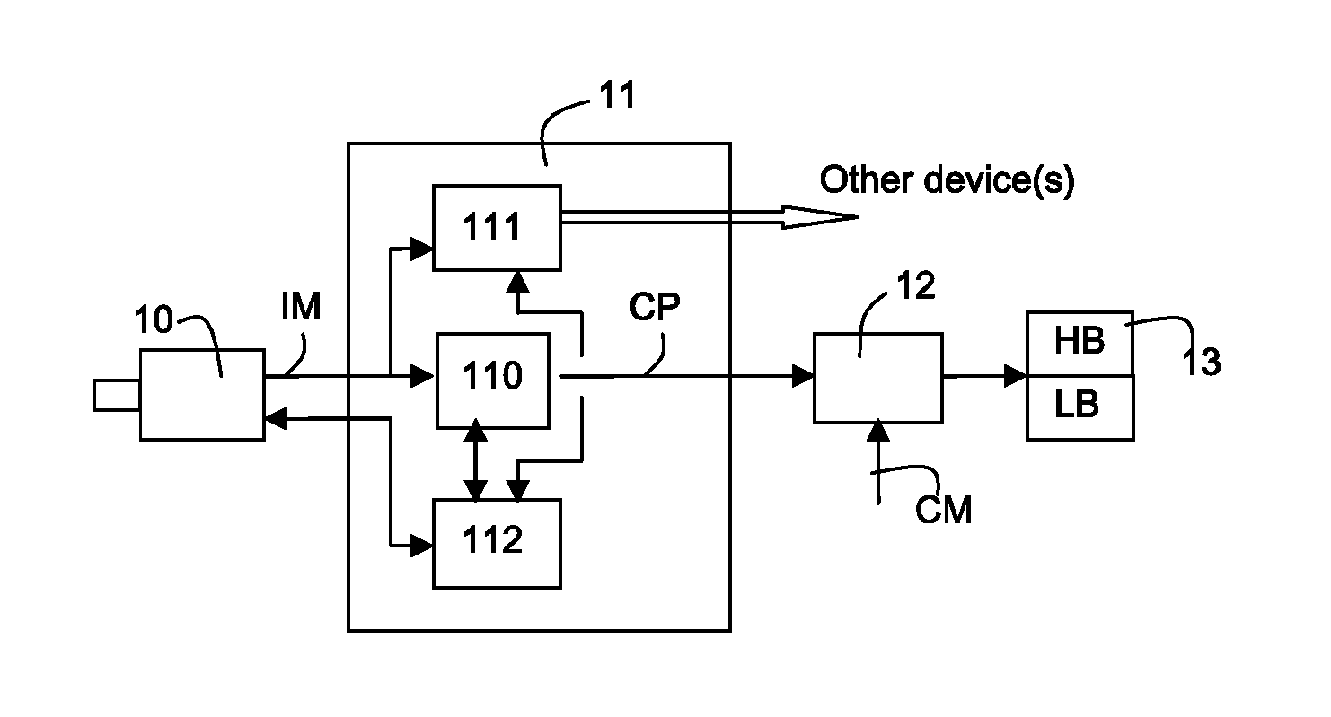
[0049]FIG. 1 shows the general structure of an automatic switching control device according to the invention,

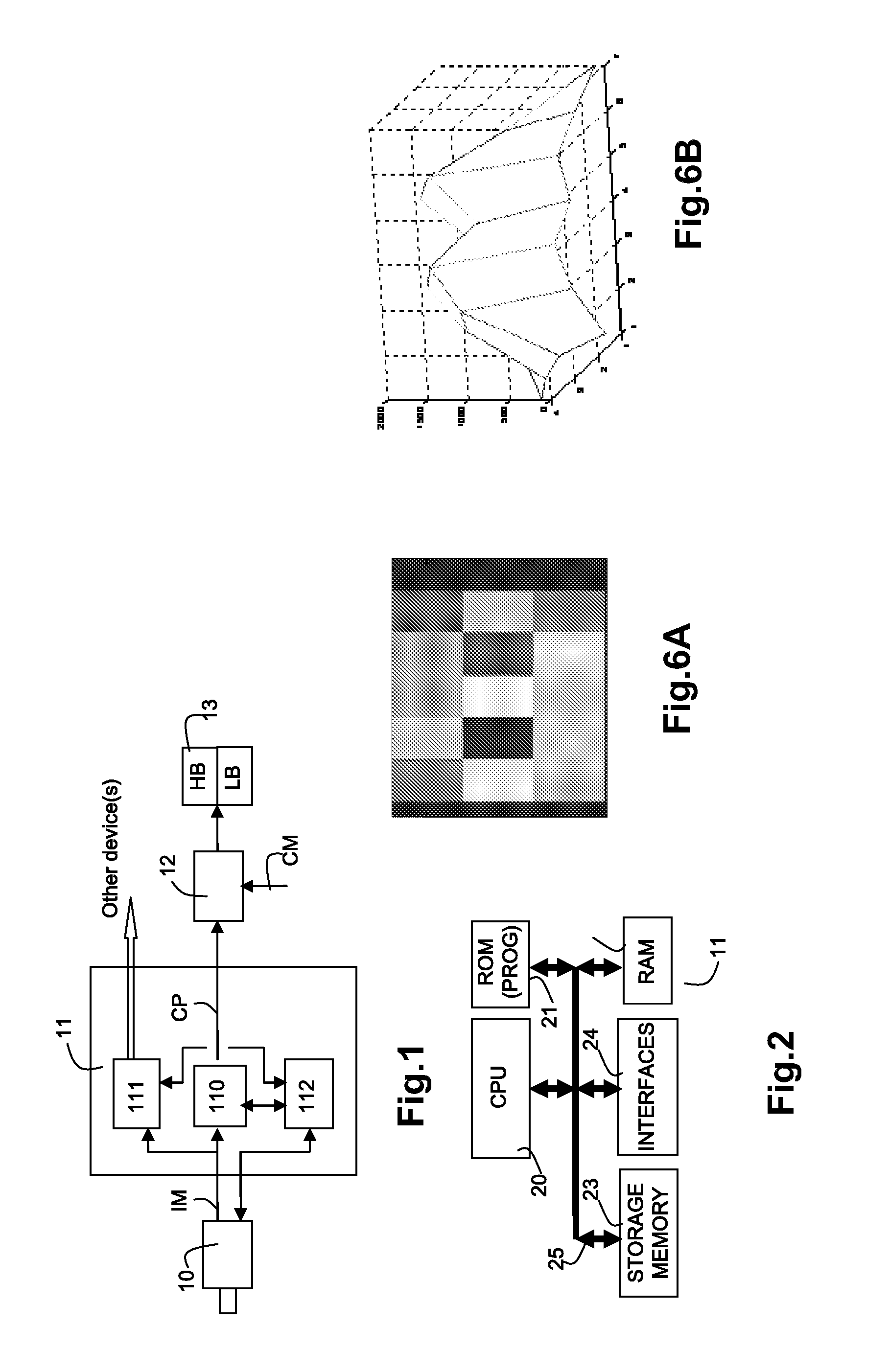
[0050]FIG. 2 shows a material configuration of a processing unit used by the invention,

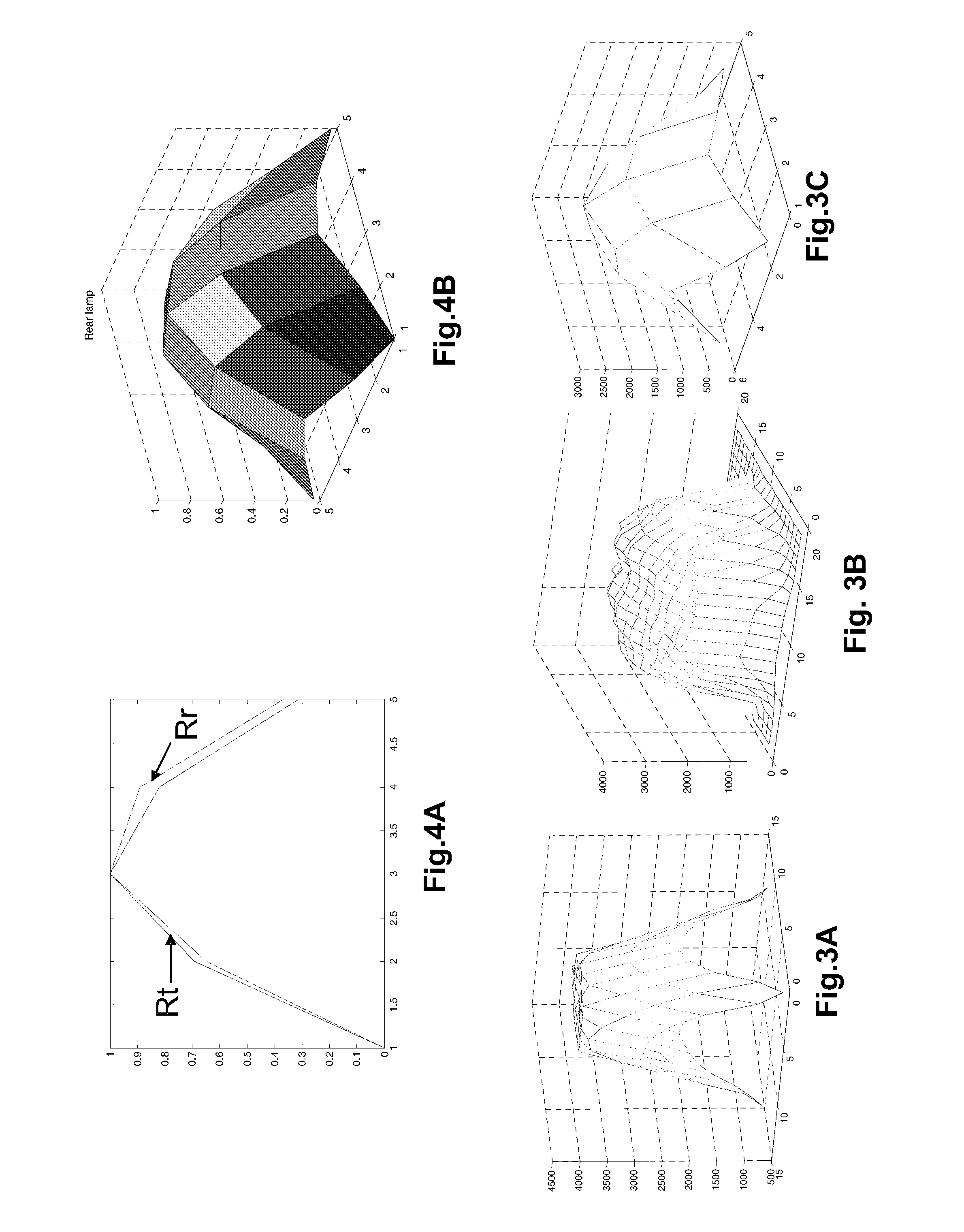
[0051]FIGS. 3A, 3B and 3C are three-dimensional representations of the variation in light intensity of three types of light source,

[0052]FIGS. 4A and 4B illustrate the processing for discerning between two types of light source,

[0053]FIG. 5 shows an algorithm for implementation of a method according to the invention, and

[0054]FIGS. 6A and 6B are two and three-dimensional representations of the variation in light intensity of another type of light source.

DESCRIPTION OF THE PREFERRED EMBODIMENTS

[0055] The invention will now be described using a non-limiting example of a device for controlling the automatic switching of the lighting projectors of a motor vehicle from a “high beam” lighting mode to a “dipped / low beam” lighting mode. With reference to FIG. 1, the device for controlling the...


PUM


Abstract

The invention relates to a method for controlling the automatic switching of the projector of a vehicle, in particular of a motor vehicle, from a first lighting mode to a second lighting mode, the method being implemented when the vehicle is driven at night and including the following steps: acquisition by a black and white sensor of images representing night-time road scenes, extraction from the images of the zones corresponding to light sources, and discrimination of the type of light sources in accordance with the distribution of the levels of light intensity in the zones.

Description

BACKGROUND OF THE INVENTION [0001] 1. Field of the Invention [0002] The invention relates generally to the field of lighting for motor vehicles. More specifically, the invention is concerned with projector control modes allowing projectors to be made to pass automatically from one operating mode to another. This may, for example, involve the automatic switching of the projectors of a vehicle from a “high beam”-type lighting state to a “low beam / dipped” lighting state when a situation is detected that is liable to dazzle the driver driving in the opposing direction or the driver of the preceding vehicle on the road in the same direction (dazzling via the rear-view mirrors). However, other types of switching are also conceivable, for example for passing from an “off” mode to a “dipped or high beam” mode. [0003] 2. Description of the Related Art [0004] The literature has already proposed on-board devices allowing dipped / high beam projector switching, devices using various types of sens...

Claims


Application Information

Patent Timeline
Patent Type & Authority Applications(United States)
IPC IPC(8): B60Q1/00
CPCB60Q1/1423B60Q2300/314B60Q2300/45B60Q2300/42B60Q2300/41
Inventor REBUT, JULIEN
Owner VALEO VISION SA
Why Eureka
Try Eureka