Moving blade for a turbomachine, the blade having a common cooling air feed cavity

a turbomachine and moving blade technology, which is applied in the direction of blade accessories, machines/engines, mechanical apparatus, etc., can solve the problems of limiting the life of the blade, difficult to provide a robust ceramic core, and significant risk of a core breaking, so as to facilitate air flow and simplify fabrication.

Inactive Publication Date: 2007-09-13
SN DETUDE & DE CONSTR DE MOTEURS DAVIATION S N E C M A
View PDF0 Cites 26 Cited by
  • Summary
  • Abstract
  • Description
  • Claims
  • Application Information

AI Technical Summary

Benefits of technology

[0006]A main object of the present invention is thus to mitigate such drawbacks by providing a moving blade provided with internal cooling circuits that are simpler to fabricate by casting and in which the flow of air is facilitated.

Problems solved by technology

Thus, for a high-pressure turbine, the temperature of the gas coming from the combustion chamber can reach values much higher than those that the moving blades of the turbine can withstand without damage, which has the consequence of limiting the lifetime of the blades.
Fabricating a gas turbine moving blade having a cooling circuit of that type by a casting process presents drawbacks.
Unfortunately, the large number of cavities needed for cooling the blade makes it difficult to provide a ceramic core that is robust.
There is therefore a significant risk that such a core will break.
A result of this curvature of the cavities is that the flow of air in the cavities is disturbed, and that impedes cooling the blade.

Method used


Image

  • Moving blade for a turbomachine, the blade having a common cooling air feed cavity
  • Moving blade for a turbomachine, the blade having a common cooling air feed cavity
  • Moving blade for a turbomachine, the blade having a common cooling air feed cavity

Examples


Embodiment Construction

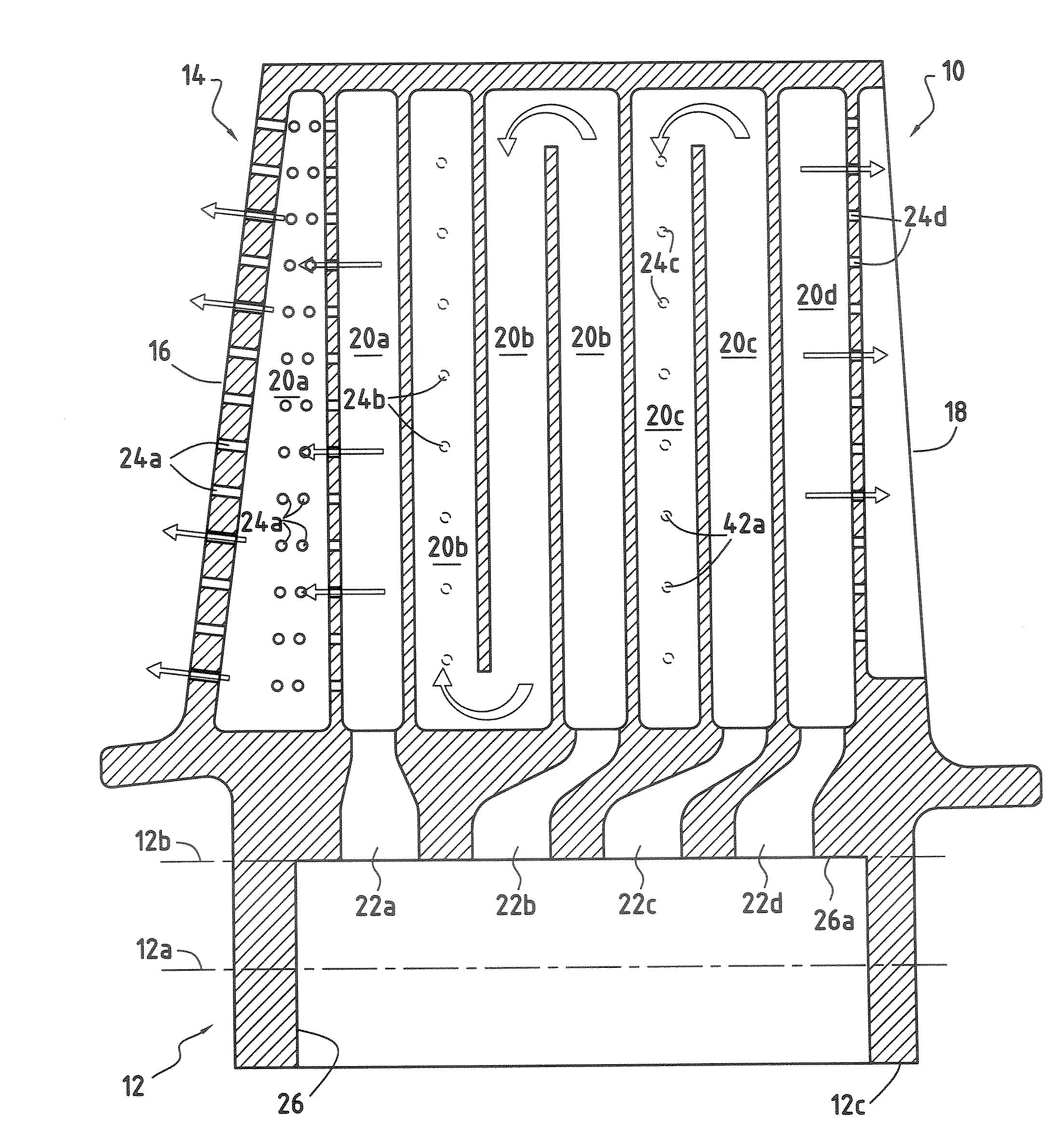
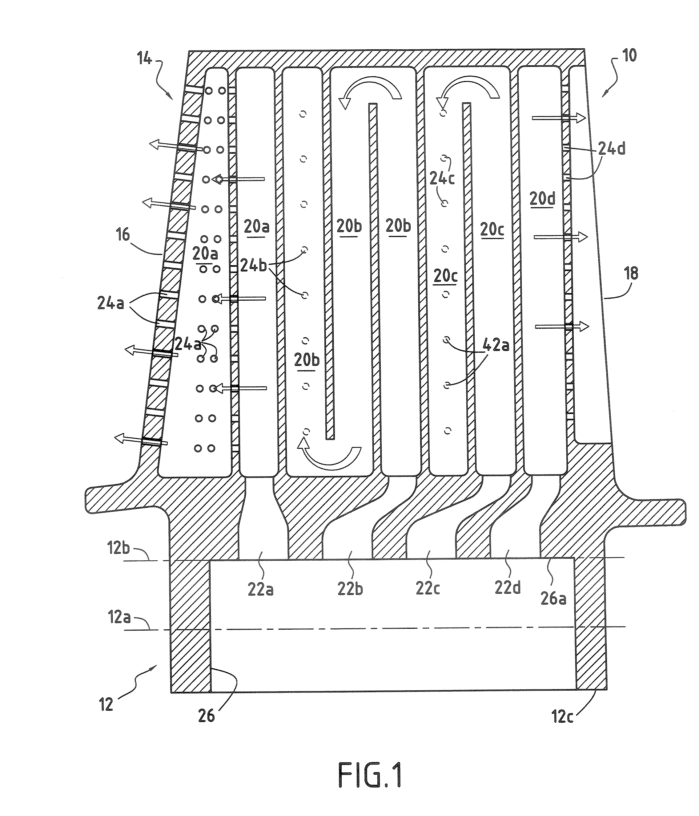
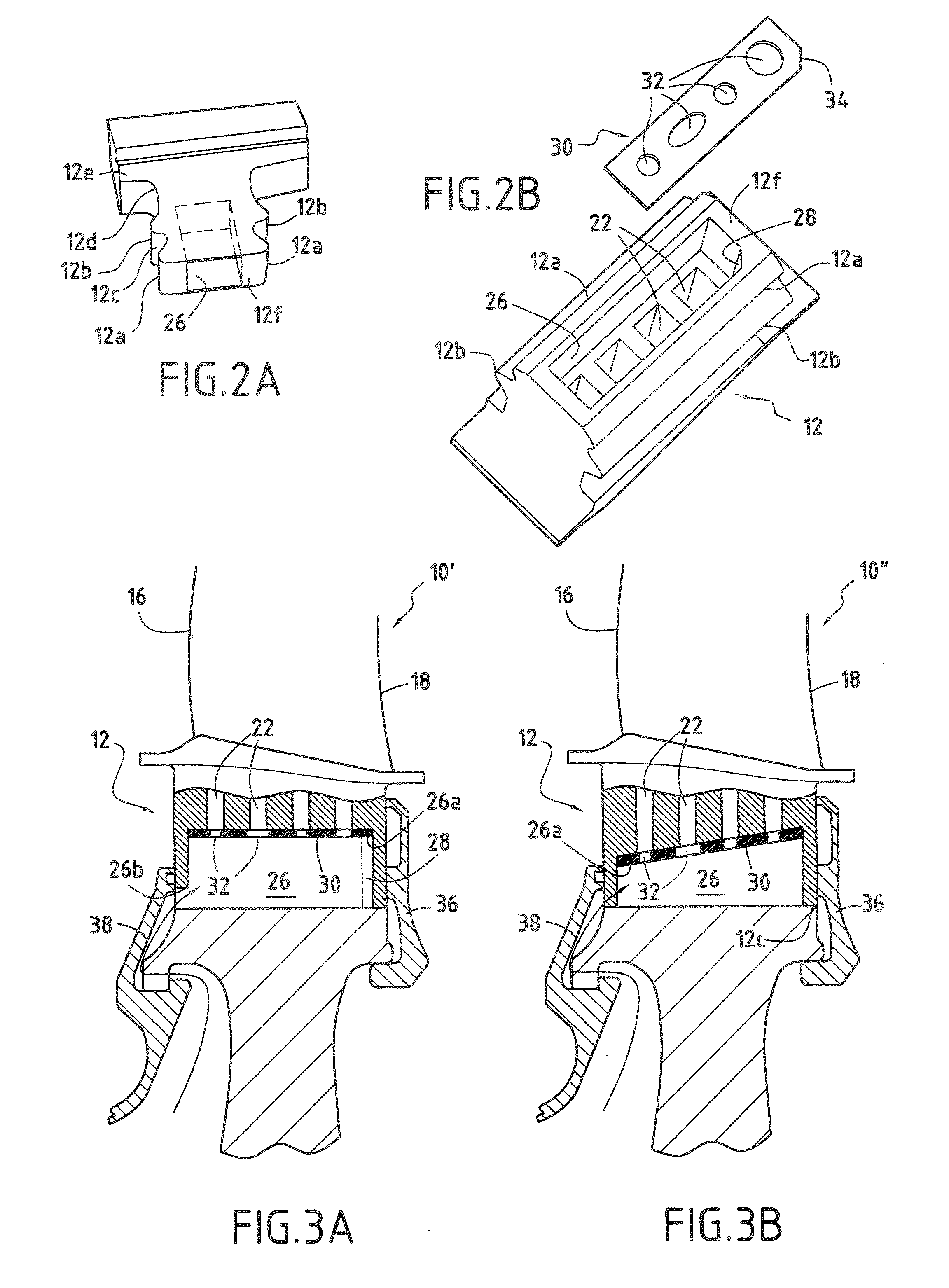
[0018]FIGS. 1, 2A, and 2B show a moving blade 10 for a turbomachine, such as a moving blade of a high-pressure turbine. Naturally, the invention can also be applied to other moving blades of the turbomachine, for example to the low-pressure turbine blades thereof.

[0019]The blade 10 has an aerodynamic surface that extends radially between the blade root 12 and a blade tip 14. This aerodynamic surface comprises a leading edge 16 placed facing the flow of hot gas coming from the combustion chamber of the turbomachine, a trailing edge 18 opposite to the leading edge 16, a pressure side face, and a suction side face, the side faces (not shown in the figures) interconnecting the leading edge 16 and the trailing edge 18.

[0020]The blade 10 also has two lower swellings (or teeth) 12a disposed laterally on either side of the blade root 12 and two upper swellings 12b also disposed laterally on either side of the root, these swellings 12a, 12b defining bearing surfaces for fastening the root in...


PUM


Abstract

A moving blade for a turbomachine, the blade comprising an aerodynamic surface extending radially between a blade root and a blade tip, and at least one internal cooling circuit made up of at least one radial cavity, at least one air admission opening formed in the blade root and opening out into the cavity(ies), and a plurality of outlet orifices opening out from the cavity(ies) and leading to the outside of the blade, the blade root having lower swellings and upper swellings defining bearing surfaces for fastening the blade to a rotor disk. The air admission openings of the cooling circuit(s) open out into a common cavity that is formed in the blade root and that extends radially from the base of the blade root at least as far as the upper swelling of said root.

Description

BACKGROUND OF THE INVENTION[0001]The present invention relates to the general field of cooling moving blades in a turbomachine, and in particular the moving blades of the high-pressure turbine.[0002]It is known to provide the moving blades of a gas turbine in a turbomachine, such as the high-pressure or the low-pressure turbine, with internal cooling circuits enabling them to withstand without damage the very high temperatures to which they are subjected while the turbomachine is in operation. Thus, for a high-pressure turbine, the temperature of the gas coming from the combustion chamber can reach values much higher than those that the moving blades of the turbine can withstand without damage, which has the consequence of limiting the lifetime of the blades.[0003]By means of such cooling circuits, air that is introduced into the blade via its root travels through the blade, following a path formed by a plurality of cavities formed in the blade, prior to being ejected through outlet...

Claims


Application Information

Patent Timeline
Patent Type & Authority Applications(United States)
IPC IPC(8): F01D5/18
CPCF01D5/082F01D5/3007F01D5/187
Inventor DIGARD BROU DE CUISSART, SEBASTIENGIOT, CHANTAL GISELEPOTIER, THOMAS
Owner SN DETUDE & DE CONSTR DE MOTEURS DAVIATION S N E C M A
Why Eureka
Try Eureka