Fuel Cell System

Inactive Publication Date: 2007-09-13
PANASONIC CORP
View PDF6 Cites 6 Cited by
  • Summary
  • Abstract
  • Description
  • Claims
  • Application Information

AI Technical Summary

Benefits of technology

[0022] According to the present invention, the fuel cell system can reduce the voltage variations of the plurality of fuel cells constituting the fuel cell stack and stabilize the generated power of the fuel cell stack by increasing or decreasing the fuel supply amount or the air supply amount every fuel cell.
[0023] In addition, according to the present invention, the fuel cell system can prevent the voltage of any fuel cell from being lowered and any fuel cell from deteriorating due to the variations in characteristics of the fuel cells constituting the fuel cell stack or variations in characteristics of the fuel supply device.
[0024] In addition, according to the present invention, the fuel cell system can prevent the current from being lowered by any one of the plurality of fuel cells constituting the fuel cell stack and prevent the generated power of the fuel cell stack from being lowered.
[0025] In addition, according to the present invention, the fuel cell system can conform the generated power of the fuel cell stack to the required power of the load device as much as possible.

Problems solved by technology

Although the current of the fuel cell can be a desired value by enlarging a reaction area, the reaction area cannot be enlarged because the power supply of a portable electronic device is required to be miniaturized.
When a load of an air compressor of an air supply source is reduced or supply of fuel gas flux is extremely reduced to enhance efficiency of a fuel cell system, a cell voltage is lowered or reversed and a fuel cell is damaged in some cases.

Method used


Image

  • Fuel Cell System
  • Fuel Cell System
  • Fuel Cell System

Examples


embodiment 1

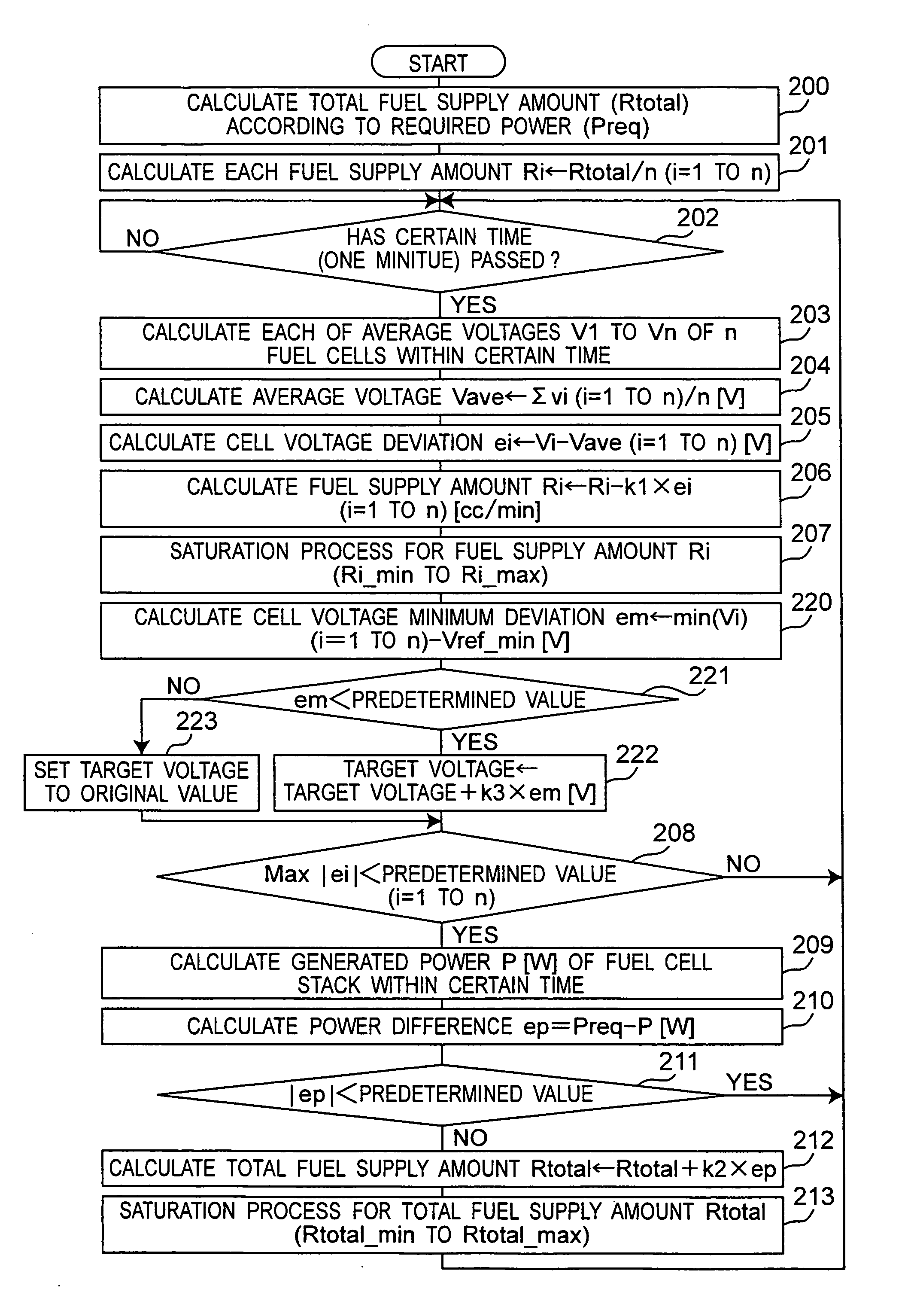
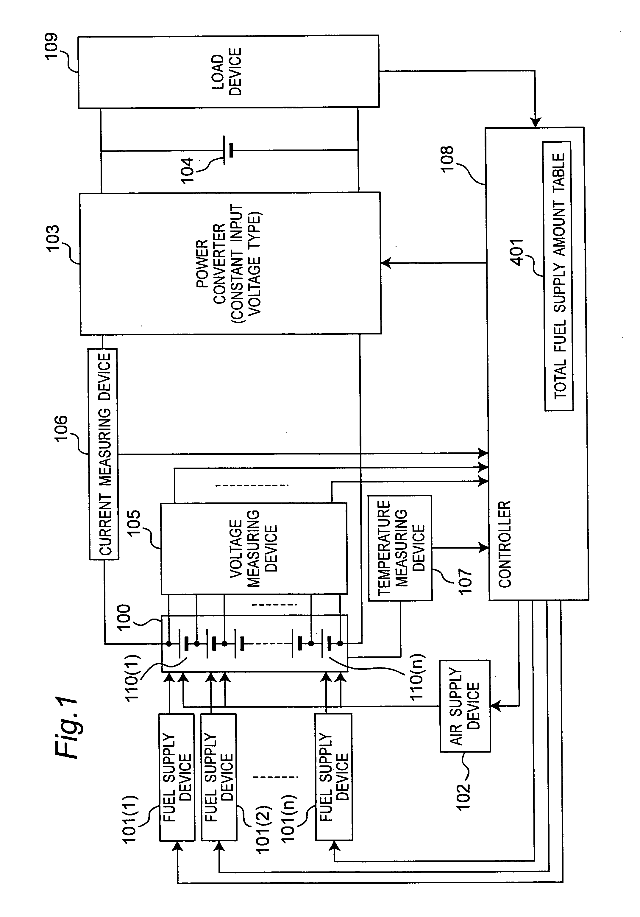
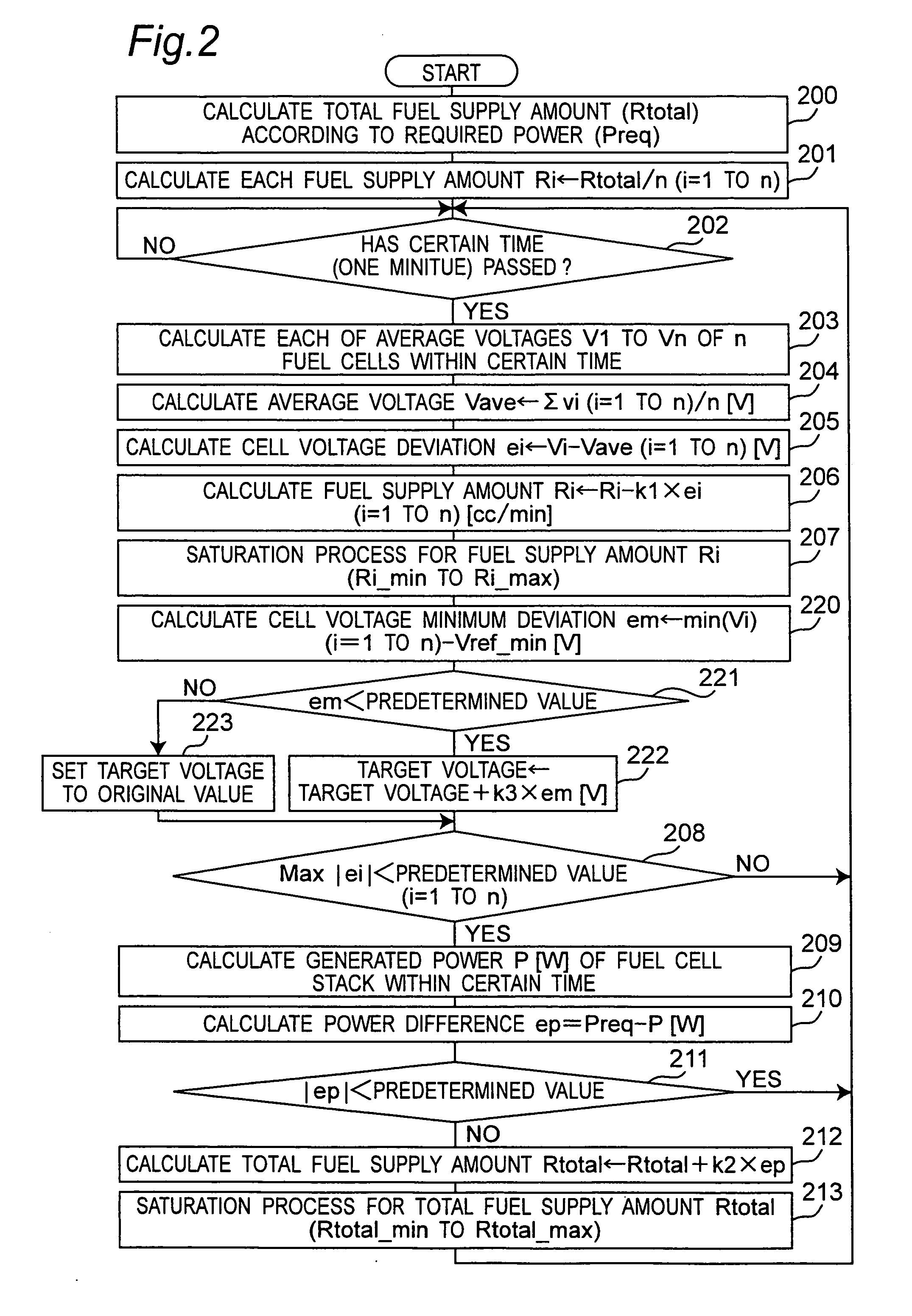
[0047] A fuel cell system according to an embodiment 1 of the present invention will be described with reference to FIGS. 1 to 4. FIG. 1 is a diagram showing a configuration of the fuel cell system according to the embodiment 1 of the present invention. As shown in FIG. 1, the fuel cell system according to the embodiment 1 of the present invention has a fuel cell stack 100 having a plurality of fuel cells, fuel supply devices 101(1) to 101(n) (n is two or more arbitrary positive integers) for supplying fuel to each fuel cell of the fuel cell stack 100, an air supply device 102 for supplying air to each fuel cell of the fuel cell stack 100, a power converter 103 for controlling a voltage of the fuel cell stack 100, a secondary cell 104 for making up for a short power when a generated power of the fuel cell stack 100 is less than a power which is required by a load device, a voltage measuring device 105 for measuring a voltage of each fuel cell of the fuel cell stack 100, a current me...

embodiment 2

[0078] A fuel cell system according to an embodiment 2 of the present invention will be described with reference to FIG. 5 to FIG. 9. FIG. 5 is a diagram showing a configuration of the fuel cell system in the embodiment 2 of the present invention. In FIG. 5, the same reference numerals denote the same components as those in FIG. 1 and their detailed descriptions will be omitted. The fuel cell system in the embodiment 2 has air supply devices 502(1) to 502(n) (n is two or more positive integers) for supplying air to fuel cells 110(1) to 110(n), respectively and one fuel supply device 501 for supplying fuel uniformly to each fuel cell. The controller 108 has a total air supply amount table 801 (FIG. 8). Except for the above configuration, the fuel cell system in the embodiment 2 is the same as that of the embodiment 1.

[0079] The fuel cell system according to the embodiment 2 controls an air supply amount to reduce voltage variations of the fuel cells 110(1) to 110(n), and stabilize a...


PUM


Abstract

There is provided a fuel cell system which reduces voltage variations of a plurality of fuel cells and stabilizes a generated power of a fuel cell stack. A fuel cell system according to the invention includes a fuel cell stack having a plurality of fuel cells connected in series, a fuel supply device, an air supply device and a controller. The controller sets at least one of a fuel supply amount and an air supply amount for each fuel cell based on each voltage of the plurality of fuel cells so that each voltage variation of the plurality of fuel cells may be minimized, and the fuel supply device supplies fuel to each of the fuel cells based on the fuel supply amount of each fuel cell, and / or the air supply device supplies air to each of the fuel cells based on the air supply amount of each fuel cell.

Description

TECHNICAL FIELD [0001] The present invention relates to a fuel cell system suitable for a power supply of an electronic device and the like. BACKGROUND ART [0002] Recently, a fuel cell which can continuously supply a power for a long time is remarked as a power supply of an electronic device and the like. The fuel cell has generally a fuel electrode and an air electrode arranged on both sides of an electrolyte layer. When hydrogen is applied to the fuel electrode and oxygen is applied to the air electrode, an electrochemical reaction is produced and a DC (direct current) current is generated. Since an electromotive force of the fuel cell which is a minimum unit for generating the current is small, it is necessary to connect a plurality of fuel cells in series to provide a power required by a device using the fuel cells as a power source. When the plurality of fuel cells are stacked to make a fuel cell stack, a great power is provided. [0003] Although the current of the fuel cell can...

Claims


Application Information

Patent Timeline
IPC IPC(8): H01M8/04
CPCH01M8/04007Y02E60/50H01M8/04365H01M8/04552H01M8/04589H01M8/04619H01M8/04753H01M8/04873H01M8/0491H01M8/0637H01M8/1011H01M16/006H01M2250/30Y02B90/18H01M8/04089Y02B90/10Y02E60/10
Inventor TAKADA, MASAHIROKOZU, KATSUMIICHINOSE, TOSHIHIKO
Owner PANASONIC CORP
Why Eureka
Try Eureka