Electric double layer capacitor

a double-layer capacitor and capacitor technology, applied in the direction of liquid electrolytic capacitors, electrochemical generators, transportation and packaging, etc., can solve the problems of low energy storage capacity of electric double-layer capacitors, large current not being allowed to flow instantaneously, and power density decline, etc., to achieve excellent cycle life, large current flow, and large power storage amoun

Inactive Publication Date: 2007-09-20
MITSUBISHI ELECTRIC CORP
View PDF6 Cites 11 Cited by
  • Summary
  • Abstract
  • Description
  • Claims
  • Application Information

AI Technical Summary

Benefits of technology

[0031]Consequently, it is possible to provide the electric double layer capacitor having an excellent cycle life and having a large power storage amount while keeping characteristics capable of instantaneously allowing large current to flow.

Problems solved by technology

However, the energy storage capacity of the electric double layer capacitor is low in comparison with a lead battery, a nickel hydrogen battery, a lithium ion battery, or the like.
However, the electrostatic capacity and an internal electric resistance become large, resulting in the large current not being allowed to flow instantaneously.
In other words, there arises a problem in that the largest advantage of the electric double layer capacitor is eliminated, because the power density thereof decreases.
However, the necessary discharge time increases, resulting in decreasing of the power density.
Further, as the internal resistance increases, thermal loss that generates during the current flow increases, so it becomes impossible to allow the large current to flow, resulting in decreasing of the power density.
However, lowering the electrostatic capacity causes lowering of the energy storage capacity, the relation being a dilemma.
Accordingly, current flowing the electric terminals and wirings generates heat to consume much of accumulated energy, thereby causing a problem in that the energy which can be taken out to an outside is markedly reduced.
However, there was a serious problem in that the cycle life of the electric double layer capacitor is markedly deteriorated when charging and discharging are repeatedly performed in comparison with the electric double layer capacitor formed of the single cell only, which is constructed of a thick electrode layer having a large electrostatic capacity and with the electric double layer capacitor formed of the single cell only, which is constructed of a thin electrode layer having a small internal resistance.

Method used


Image

  • Electric double layer capacitor
  • Electric double layer capacitor
  • Electric double layer capacitor

Examples


first embodiment

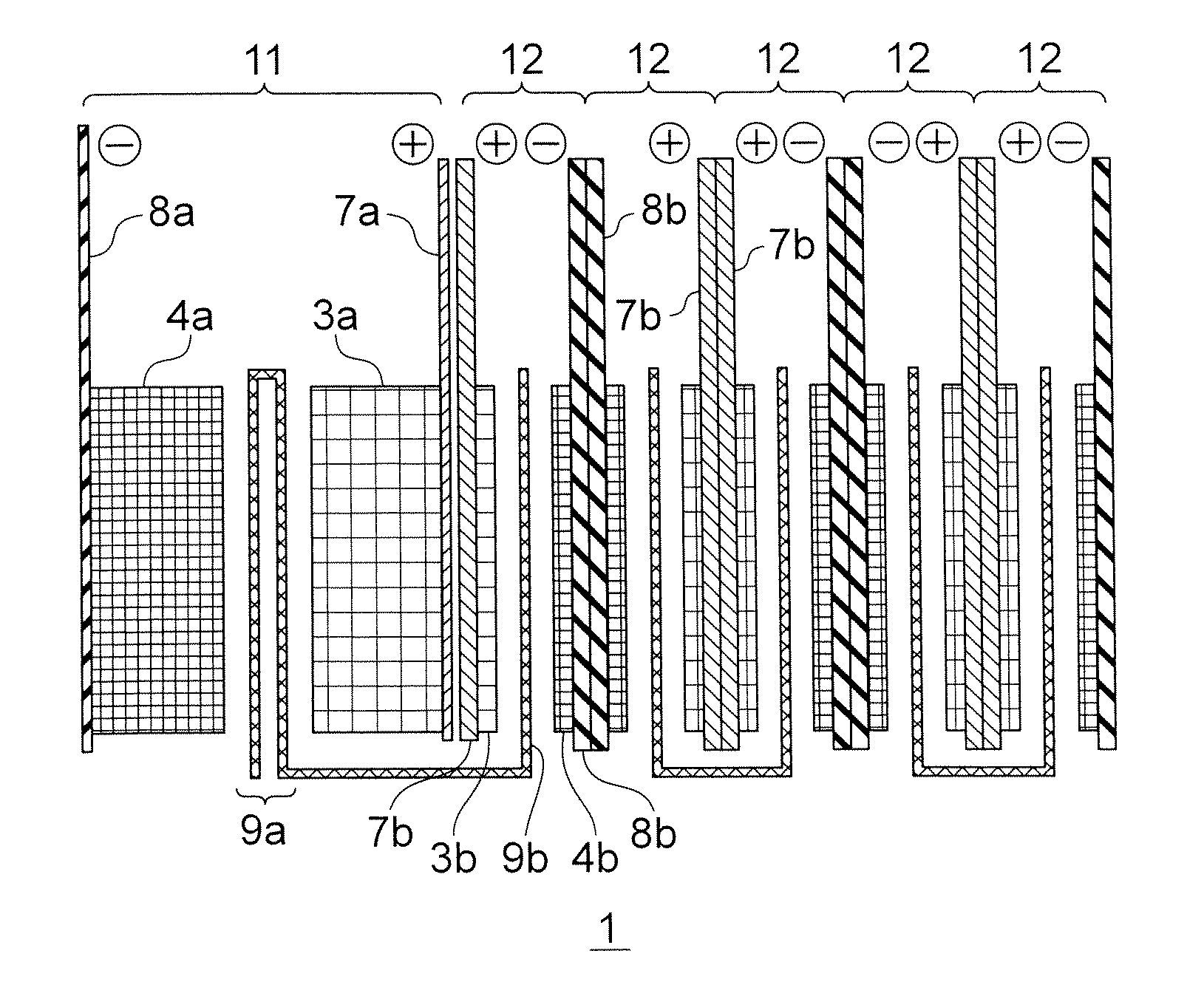
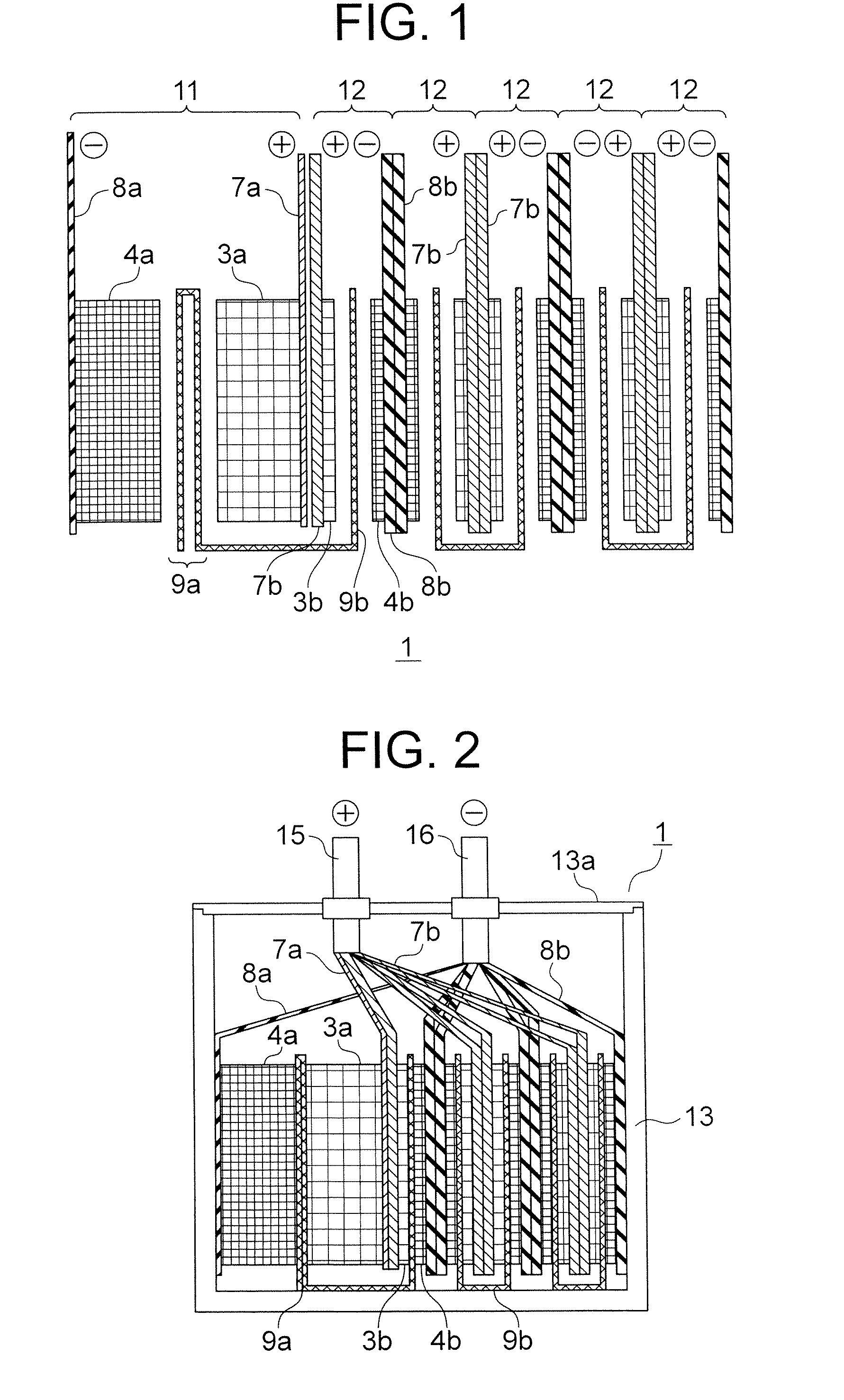
[0047]FIG. 1 is a sectional view showing a structure of an electric double layer capacitor according to a first embodiment of the present invention.

[0048]The electric double layer capacitor 1 according to the first embodiment of the present invention, as shown in FIG. 1, is constructed of: one single cell (hereinafter, referred to as “large capacity single cell”) 11, in which a positive electrode layer 3a having a thick electrode layer and a large electrostatic capacity (hereinafter, referred to as “large capacity positive electrode layer”) 3a and a negative electrode layer 4a having a thick electrode layer and a large electrostatic capacity (hereinafter, referred to as “large capacity negative electrode layer”) 4a are arranged; and five singe cells (hereinafter, referred to as “small capacity single cell”) 12, in each of which a positive electrode layer 3b having a thin electrode layer and a small electrostatic capacity (hereinafter, referred to as “small capacity positive electrod...

second embodiment

[0106]Each of FIGS. 4A to 4C is a sectional view showing a structure of single cells of an electric double layer capacitor according to a second embodiment of the present invention.

[0107]An electric double layer capacitor 1B according to a second embodiment of the present invention is different from the electric double layer capacitor 1 according to the first embodiment of the present invention in that the number of the large capacity single cell 11 and the small capacity single cells 12 are limited. However, the other structure is the similar to the first embodiment of the present invention, therefore, the description thereof is omitted while assigning the same reference symbols to the similar parts.

[0108]The electric double layer capacitor 1B according to the second embodiment of the present invention fixes the number of the large capacity single cell 11 at one, and limits the number of the small capacity single cells 12 to zero (not shown), one (shown in FIG. 4A), three (shown in...

third embodiment

[0113]FIG. 6 is a sectional view showing a structure of an electric double layer capacitor according to a third embodiment of the present invention.

[0114]An electric double layer capacitor 1C according to the third embodiment of the present invention is different from the electric double layer capacitor 1 according to the first embodiment of the present invention in that the number of the large capacity single cells 11B and the thickness of the large capacity positive electrode layer 3Ba and the large capacity negative electrode layer 4Ba. However, the other components are similar to those of the first embodiment of the present invention, therefore, the description thereof is omitted while assigning the same reference symbols to the similar parts.

[0115]According to the third embodiment of the present invention, the thickness of the large capacity positive electrode layer 3Ba and the large capacity negative electrode layer 4Ba of each of the large capacity single cells 11B is 0.4 mm,...


PUM


Abstract

Provided is an electric double layer capacitor including a large capacity single cell having a large electrostatic capacity and a small capacity single cell are connected to the same exterior case in parallel, and a thickness of a separator of the large capacity single cell is made thicker than a thickness of a separator of the small capacity single cell. With this structure, a supply amount of an electrolyte solution to the large capacity single cell is markedly increased compared with the small capacity single cell, thereby being capable of preventing degradation of the large capacity single cells and the small capacity single cells and providing the electric double layer capacitor having an excellent cycle life and having a large power storage amount while keeping characteristics capable of instantaneously allowing large current to flow.

Description

BACKGROUND OF THE INVENTION[0001]1. Field of the Invention[0002]The present invention relates to an electric double layer capacitor, and more particularly, to an electric double layer capacitor in which electric charge is accumulated within an electric double layer formed on an interface between an electrolytic solution and a polarized electrode.[0003]2. Description of the Related Art[0004]An electric double layer capacitor has various forms such as a layered type, a cylindrical type, and a button type. However, basically, the electric double layer capacitor is provided with a plurality of single cells (hereinafter, a constructional component having a positive electrode layer and a negative electrode layer, which are formed so as to face with each other through a separator, is referred to as “single cell”) formed of positive electrode layers and negative electrode layers each containing as main components carbon particles such as activated carbon formed on a surface of the electric ...

Claims


Application Information

Patent Timeline
Patent Type & Authority Applications(United States)
IPC IPC(8): H01L29/94H01G11/10B82Y99/00H01G11/12H01G11/22H01G11/24H01G11/32H01G11/34H01G11/36H01G11/38H01G11/42H01G11/52H01G11/66H01G11/76H01G11/86
CPCH01G9/016H01G9/02H01G9/14H01G9/155H01G11/04Y02T10/7022H01G11/12H01G11/52H01G11/72Y02E60/13H01G11/10Y02T10/70H01G11/74
Inventor MITSUDA, KENROSUGA, IKUROMATSUMOTO, SADAYUKISETO, MAKOTOOCHI, NAOKITAKUMA, YOSHIYUKI
Owner MITSUBISHI ELECTRIC CORP
Why Eureka
Try Eureka