Linear regulator circuit

a regulator circuit and regulator circuit technology, applied in the direction of electric variable regulation, process and machine control, instruments, etc., can solve the problem that the psrr characteristic of the ldo circuit cannot be improved, and achieve the effect of suppressing high frequency fluctuations, suppressing low frequency fluctuations in the output voltage vo, and lowering the power supply rejection ratio (psrr)

Inactive Publication Date: 2007-09-20
FUJITSU LTD
View PDF4 Cites 24 Cited by
  • Summary
  • Abstract
  • Description
  • Claims
  • Application Information

AI Technical Summary

Benefits of technology

[0018]The capacitor C1 contributes to suppressing high frequency fluctuations in the output voltage Vo, and the error amplifier 1 contributes to suppressing low frequency fluctuations in the output voltage Vo. However, intermediate frequency fluctuations are not suppressed by the capacitor C1 and the error amplifier 1. This lowers the effect of suppressing fluctuations in the output voltage Vo and decreases the PSRR. The same problem also occurs in the LDO circuit 200 shown in FIG. 4.

Problems solved by technology

Japanese Laid-Open Patent Publication No. 2001-159922 and in Japanese Laid-Open Patent Publication No. 2002-112535 do not solve the above problems.
Therefore, the PSRR characteristic of the LDO circuit cannot be improved.

Method used


Image

  • Linear regulator circuit
  • Linear regulator circuit
  • Linear regulator circuit

Examples


Embodiment Construction

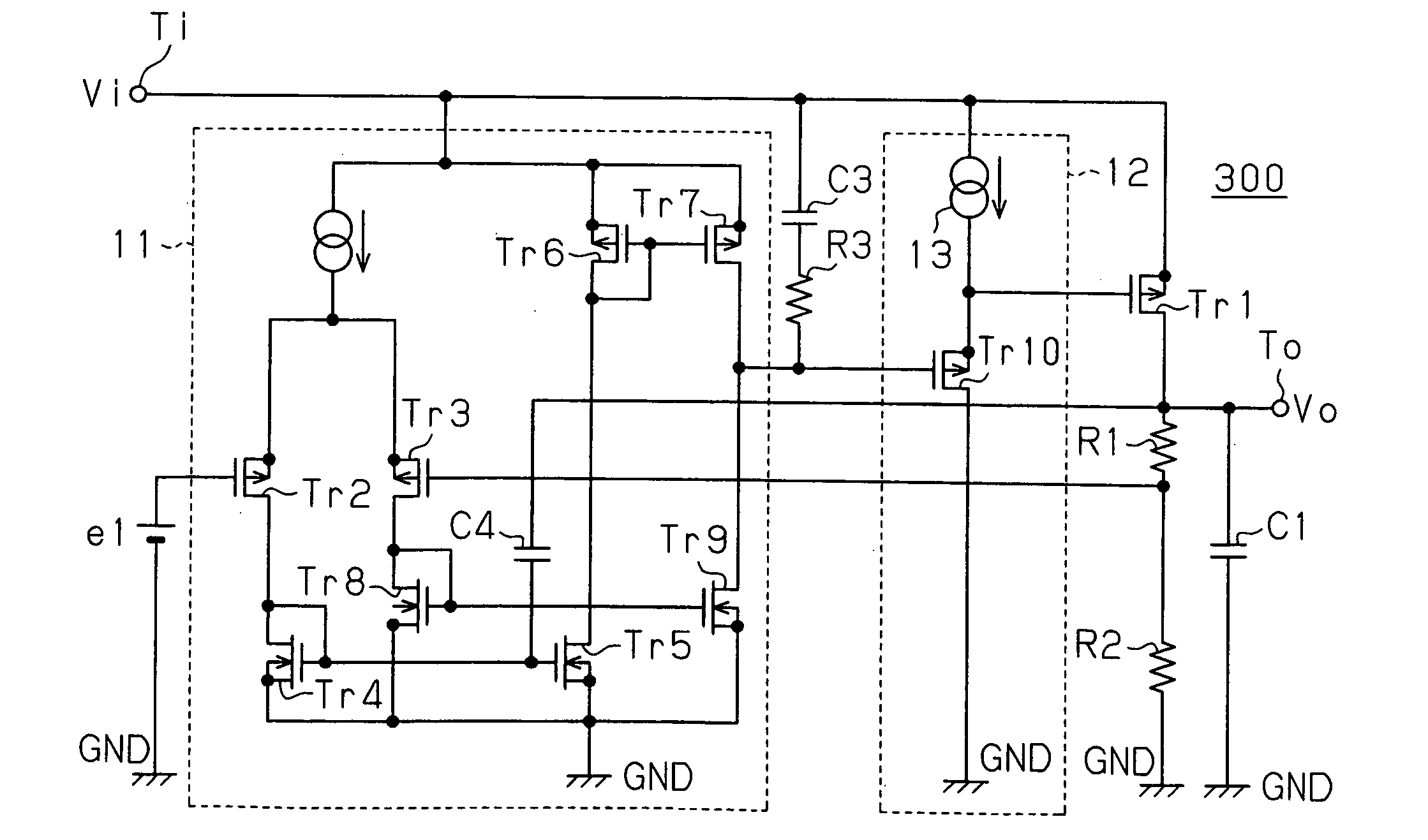
[0035]FIG. 5 is a schematic circuit diagram of an LDO circuit 300 according to a first embodiment of the present invention. In the first embodiment, the output signal of an error amplifier 11 is provided to the gate (control terminal) of an output transistor Tr1 via a buffer circuit 12. A capacitor (first capacitor) C3 and a resistor R3 are connected in series between the source (first terminal) of the output transistor Tr1 that receives the input voltage Vi and the output terminal of the error amplifier 11.

[0036]The buffer circuit 12 stably provides the output signal of the error amplifier 11 to the gate of the output transistor Tr1. Accordingly, the buffer circuit 12 has a gain of one.

[0037]Resistors R1 and R2 are connected in series between the drain (second terminal) of the output transistor Tr1 and ground GND. Node N1 located between the resistors R1 and R2 is connected to the positive input terminal (first input terminal) of the error amplifier 11. The reference voltage e1 is ...


PUM


Abstract

A linear regulator circuit for suppressing power supply noise that propagates to an output voltage. An LDO circuit functioning as the linear regulator circuit is provided with an output transistor including a source for receiving input voltage, a drain for outputting the output voltage, and a control terminal. An error amplifier powered by the input voltage generates a control voltage for controlling the output transistor based on a potential difference between a feedback voltage, which corresponds to the output voltage, and a reference voltage. A first capacitor and a resistor are connected in series between the source of the output transistor and an output terminal of the error amplifier.

Description

CROSS-REFERENCE TO RELATED APPLICATIONS[0001]This application is based upon and claims the benefit of priority from the prior Japanese Patent Application No. 2006-073564, filed on Mar. 16, 2006, the entire contents of which are incorporated herein by reference.BACKGROUND OF THE INVENTION[0002]The present invention relates to a linear regulator circuit, and more particularly, to a low drop out (LDO) circuit, which is a type of linear regulator circuit that generates a constant voltage.[0003]An LDO circuit, powered by input voltage, generates a constant voltage that is close to the input voltage. The LDO circuit detects output voltage of an output transistor with an error amplifier and controls the output transistor so as to compensate for fluctuations in the output voltage. Fluctuations in the output voltage that are caused by fluctuations in the input voltage must be accurately suppressed in the LDO circuit.[0004]FIG. 1 is a schematic circuit diagram of an LDO circuit 100 in the pri...

Claims


Application Information

Patent Timeline
Patent Type & Authority Applications(United States)
IPC IPC(8): G05F1/00
CPCG05F1/575
Inventor TSUCHIYA, CHIKARANISHIMORI, EIJI
Owner FUJITSU LTD
Why Eureka
Try Eureka