

Magnetic resonance force microscope
a magnetic resonance force and microscope technology, applied in the direction of mechanical roughness/irregularity measurement, using reradiation, instruments, etc., can solve the problems of not being able to locate the position of this portion in the whole sample, not being able to identify, and being unable to determine which one of them is exactly responsibl
- Summary
- Abstract
- Description
- Claims
- Application Information
AI Technical Summary
Benefits of technology
Problems solved by technology
Method used
Image

Examples
embodiment 1
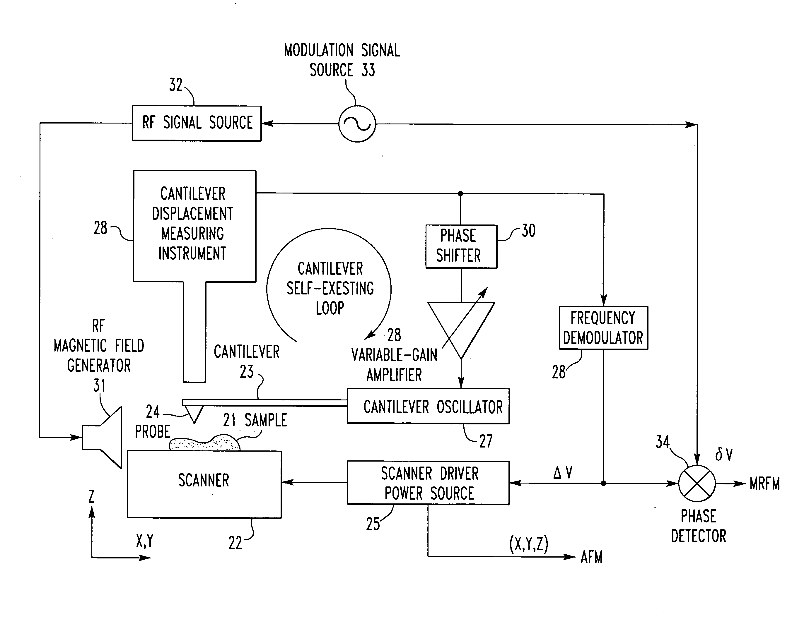
[0050] Embodiment 1 in which a superimposition of an atomic force microscope (AFM) image and a magnetic resonance force microscope (MRFM) image is obtained is first described.
[0051] The measured AFM image is a trace of the probe scanned on the surface of the sample, the trace being made while controlling the distance between the probe and the surface of the sample such that the resonant frequency of the cantilever is kept constant. The method of obtaining this image is based on a non-contact FM detection method that is a general method in atomic force microscopy. A draft version of the FM detection method is described by T. R. Albrecht, P. Gruetter, D. Home and D. Rugar, “Frequency modulation detection using high-Q cantilevers for enhanced force microscope sensitivity”, J. Appl. Phys. 69 (1991), pp. 668-673. The amount of shift Δν of the resonant frequency of the cantilever is in proportion to the gradient of the force applied to the cantilever as given by Eq. (1). δ vv0=-12k∂...
embodiment 2
[0097] Embodiment 2 for obtaining a superimposition of an atomic force microscope (AFM) image and a magnetic resonance force microscope (MRFM) image is next described.
[0098] The measured AFM image is a trace of the probe scanned over the surface of the sample while controlling the distance between the probe and the surface of the sample such that the resonant frequency of the cantilever is kept constant. The method of obtaining the image is based on a general, non-contact FM detection method in AFM. The amount of shift Δν of the resonant frequency of the cantilever is in proportion to the gradient of the force applied to the cantilever as given by Eq. (1). Therefore, in the image derived by this method, a curved plane on which the gradient of the force produced between the probe and the surface of the sample is constant is drawn.
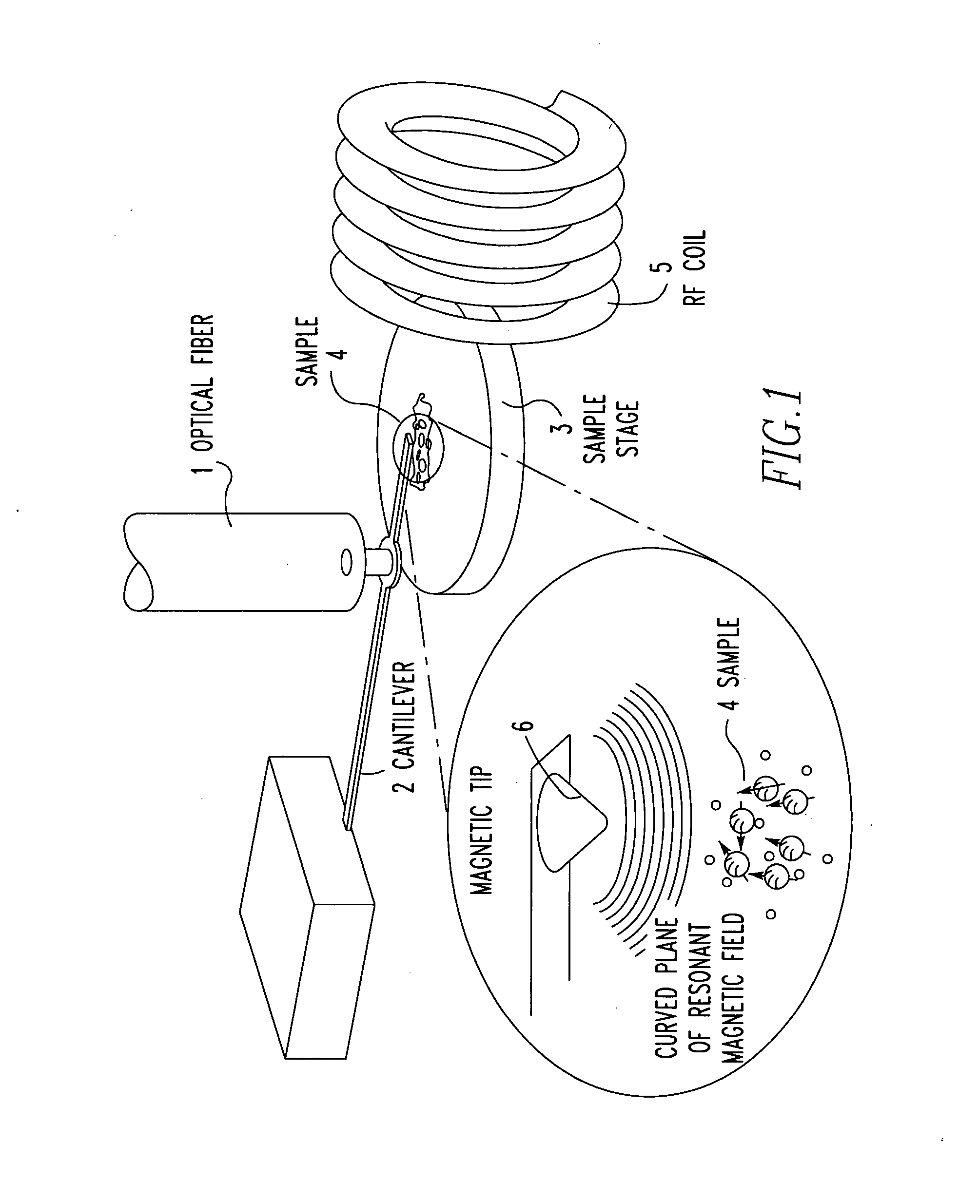
[0099] The measured MRFM image is next described briefly. Spins in the sample are controlled by a magnetic resonance technique, and a magnetic resonance f...
embodiment 3
[0125] Embodiment 3 in which a superimposition of an atomic force microscope (AFM) image and a magnetic resonance force microscope (MRFM) image is obtained is next described.
[0126] The measured AFM image is a trace of the probe scanned on the surface of the sample, the trace being made while controlling the distance between the probe and the surface of the sample such that the resonant frequency of the cantilever is kept constant. The method of obtaining this image is based on a non-contact FM detection method that is a general method in atomic force microscopy. The amount of shift Δν of the resonant frequency of the cantilever is in proportion to the gradient of the force applied to the cantilever as given by Eq. (1). Therefore, in the image derived by this method, a curved plane on which the gradient of the force produced between the probe and the surface of the sample is constant is drawn. Furthermore, as given in Eq. (4), a proportional relationship exists between the amount of...
PUM
 Abstract
Description
Claims
Application Information