Optical information recording/reproducing apparatus

Inactive Publication Date: 2007-09-20
CANON KK
View PDF52 Cites 30 Cited by
  • Summary
  • Abstract
  • Description
  • Claims
  • Application Information

AI Technical Summary

Benefits of technology

[0036]The present invention has been made in view of the above-mentioned circumstances, and therefore, an object of the present invention is to provide an optical information recording/reproducing apparatus which is

Problems solved by technology

However, there arises a drawback that an error in the thickness of the super-hemispherical lens 102-b cannot be allowed to be higher than about 1 μm.
However, it is necessary to extremely severely control a manufacture error in the thickness of the lens SIL.
Since the protective layer that prevents the recording layer from being damaged by an abrasion requires at least about several μm, production of the protective layer by using the inorganic material requires high costs.
Likewise, in the case of using the super-hemispherical SIL, it is difficult to provide a multi-layer structure that laminates plural recording layers on each other with an intermediate layer made of the organic material.
In addition, a manufacture error of the hem

Method used


Image

  • Optical information recording/reproducing apparatus
  • Optical information recording/reproducing apparatus
  • Optical information recording/reproducing apparatus

Examples


embodiment 1

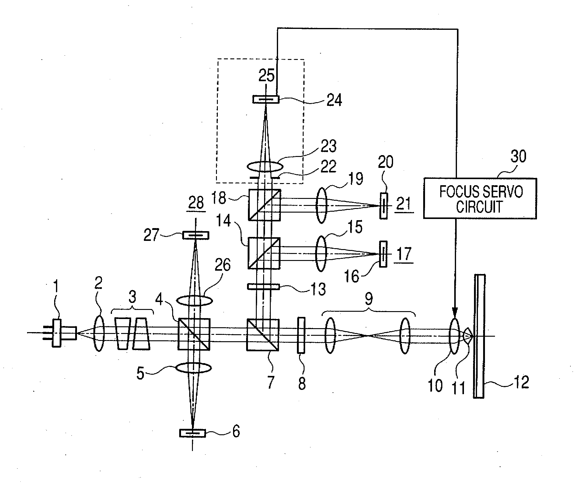
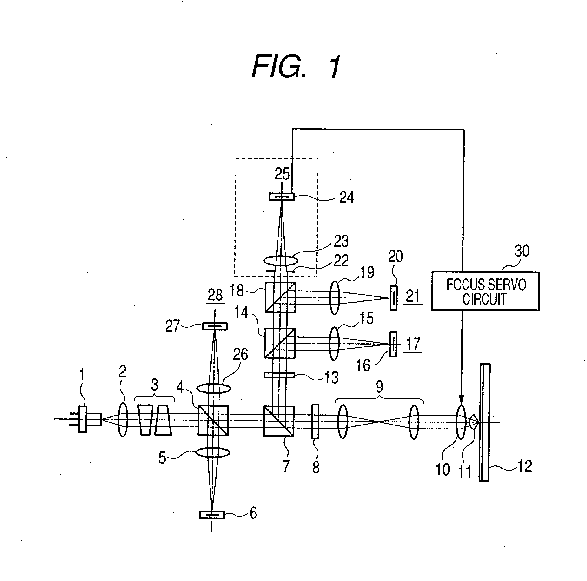
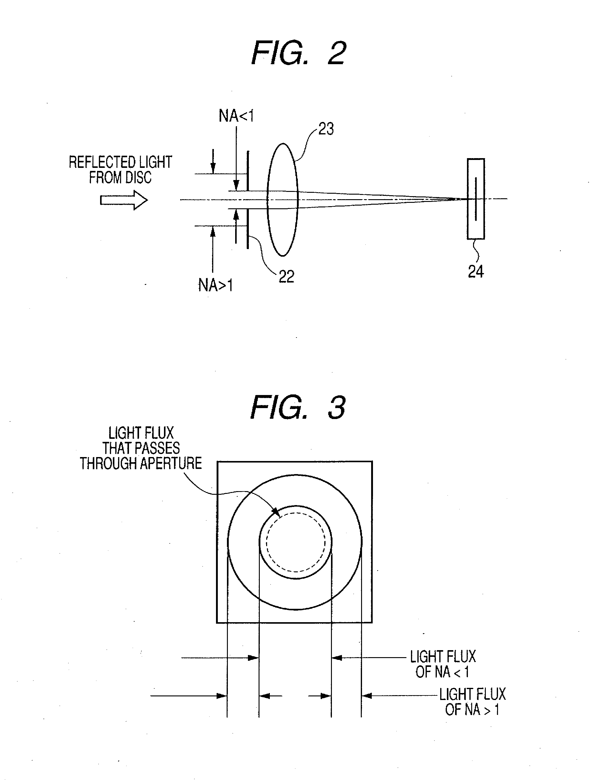
[0064]Embodiment 1 of the present invention will be described with reference to FIGS. 1 to 3. FIG. 1 illustrates the configuration of an optical pickup for near field recording in an optical information recording / reproducing apparatus according to the present invention. In FIG. 1, the same parts as those in the conventional apparatus are denoted by identical symbols.

[0065]Further, FIG. 1 shows a focus servo control circuit 30, and a recording circuit and a reproducing circuit which are required to record or reproduce information on an optical disc, a servo control circuit, and a circuit and a mechanism that conduct seek control of an optical pickup are not shown in FIG. 1. Further, other circuits and mechanisms such as a motor that rotationally drives the optical disc and a controller that controls the respective parts within the apparatus are also not shown in FIG. 1.

[0066]A light flux that is output from a semiconductor laser 1 having a wavelength of 405 nm is converted into a col...

embodiment 2

[0092]FIG. 4 is a structural diagram showing Embodiment 2 of the present invention. In FIG. 4, the same parts as those of FIG. 1 are denoted by identical symbols. Likewise, a focus servo control circuit 30, and a recording circuit and a reproducing circuit which are required to record or reproduce information on an optical disc, a servo control circuit, and a circuit and a mechanism that conduct seek control of an optical pickup are not shown in FIG. 4. Further, the focus servo circuit 30 is not shown in FIG. 4. Further, other circuits and mechanisms such as a motor that rotationally drives the optical disc and a controller that controls the respective parts within the apparatus are well known, and therefore are not shown in FIG. 4.

[0093]A light flux that is output from a semiconductor laser 1 having a wavelength of 405 nm is converted into a collimated light flux by a collimator lens 2, and input to the beam shaping prism 3 to provide an isotropic light quantity distribution. The l...

embodiment 3

[0108]This embodiment provides an optical information recording / reproducing apparatus that is capable of precisely focusing the light flux on the double-layer optical disc according to the focus error signal, and also is capable of correcting the spherical aberration at the same time so as to enable the rapid and stable interlayer jumping operation.

[0109]Embodiment 3 of the present invention will be described with reference to FIGS. 5 to 8. FIG. 5 is a diagram for explaining the configuration of the optical information recording / reproducing apparatus for near field recording according to the present invention.

[0110]A light flux that is output from a semiconductor laser 1 having a wavelength of 405 nm is converted into a collimated light flux by the collimator lens 2, and input to the beam shaping prism 3 to provide an isotropic light quantity distribution. The light flux that has been transmitted by the polarization beam splitter (PBS) 7 through the non-polarization beam splitter (N...


PUM


Abstract

There is provided an optical information recording/reproducing apparatus including a unit for detecting the focus error signal from the reflected light flux from a recording layer of an optical recording medium, and a unit for focusing the light flux on the recording layer of the optical disk on the basis of the focus error signal. In the case of detecting the focus error signal, the light flux of the effective numeric aperture NAeff<1 due to an objective lens and the SIL within a pupil is obtained by a splitting device as the focus error signal, whereby it is possible to suppress the reflected light from the bottom surface of the SIL from being mixed into the focus error signal as a noise.

Description

BACKGROUND OF THE INVENTION[0001]1. Field of the Invention[0002]The present invention relates to an optical information recording / reproducing apparatus such as an optical disc device, and more particularly, to an optical information recording / reproducing apparatus for recording or reproducing information on a recording layer of an optical recording medium using a solid immersion lens (hereinafter referred to as “SIL”).[0003]2. Description of the Related Art[0004]In general, in order to improve the recording density of an optical disc, a demand is made to shorten the wavelength of a light used in recording and reproduction, increase a numeric aperture (NA) of an objective lens, and decrease an optical spot diameter on an optical disc recording surface.[0005]As one method of meeting the above-mentioned demand, an attempt has been made in which a front lens of objective lenses comes close to the recording surface to the degree of a fraction of divers of the recording wavelength to cons...

Claims


Application Information

Patent Timeline
IPC IPC(8): G11B7/00
CPCG11B7/08511G11B7/1353G11B7/1369G11B7/1376G11B2007/13727G11B7/1387G11B7/13925G11B2007/0013G11B7/1381
Inventor KOYAMA, OSAMUNISHIKAWA, KOICHIROTORII, SHINNOSUKENAGURA, CHIHIROHORIGUCHI, HARUHIKO
Owner CANON KK
Why Eureka
Try Eureka