
Solid-state suspension laser

a laser and solid-state technology, applied in lasers, laser details, active medium materials, etc., can solve the problems of high-energy weapon-class laser systems, large platforms, and high cost, and achieve optimal absorption efficiency, optimal extraction efficiency, and optimal extraction efficiency

Inactive Publication Date: 2007-09-20
OL SECURITY LIABILITY CO
View PDF7 Cites 4 Cited by
  • Summary
  • Abstract
  • Description
  • Claims
  • Application Information

AI Technical Summary

Benefits of technology

This design enhances thermal management, simplifies fabrication, and increases power scalability, enabling high-energy, high-power operation with improved optical quality and efficiency, suitable for tactical applications.

Problems solved by technology

The implementation of a high-energy weapon-class laser system is currently limited to large platforms due to the relatively low power per weight ratio numbers in the present approaches.
The chemical laser is a highly complex system and typically takes up a good portion of the available real estate in an aircraft.
In addition, the chemical handling makes this an extremely cumbersome and undesirable approach.
Solid-state lasers, however, have their share of problems.
In addition, the gain elements themselves are currently comprised of complex, composite slabs that are very expensive and prone to damage.
Large size solid-state laser active media are required for power / energy scaling of laser systems, but such media is difficult to fabricate.
Furthermore, the large size of the gain medium makes it harder for thermal management to extract heat out of the medium.
The large gain medium also makes it more difficult to control optical uniformity, making it harder to control laser beam quality.
Finally, the MOPA approach limits the ultimate optical (and, therefore, the overall) conversion efficiency, which results in increased power and wastes heat extraction real estate.
Thermal management, however, remains a problem for this approach.
In addition, pumping for the multiple disk laser can be difficult to arrange.
Fiber lasers, however, are ultimately limited by the maximum power at which they can operate due to intensity damage threshold limits.
This, however, requires phasing of multiple fiber oscillators, which adds a number of problems (not satisfactorily solved yet) and associated complexities.

Method used


Image

  • Solid-state suspension laser
  • Solid-state suspension laser
  • Solid-state suspension laser

Examples


Embodiment Construction

[0020] Illustrative embodiments and exemplary applications will now be described with reference to the accompanying drawings to disclose the advantageous teachings of the present invention.

[0021] While the present invention is described herein with reference to illustrative embodiments for particular applications, it should be understood that the invention is not limited thereto. Those having ordinary skill in the art and access to the teachings provided herein will recognize additional modifications, applications, and embodiments within the scope thereof and additional fields in which the present invention would be of significant utility.

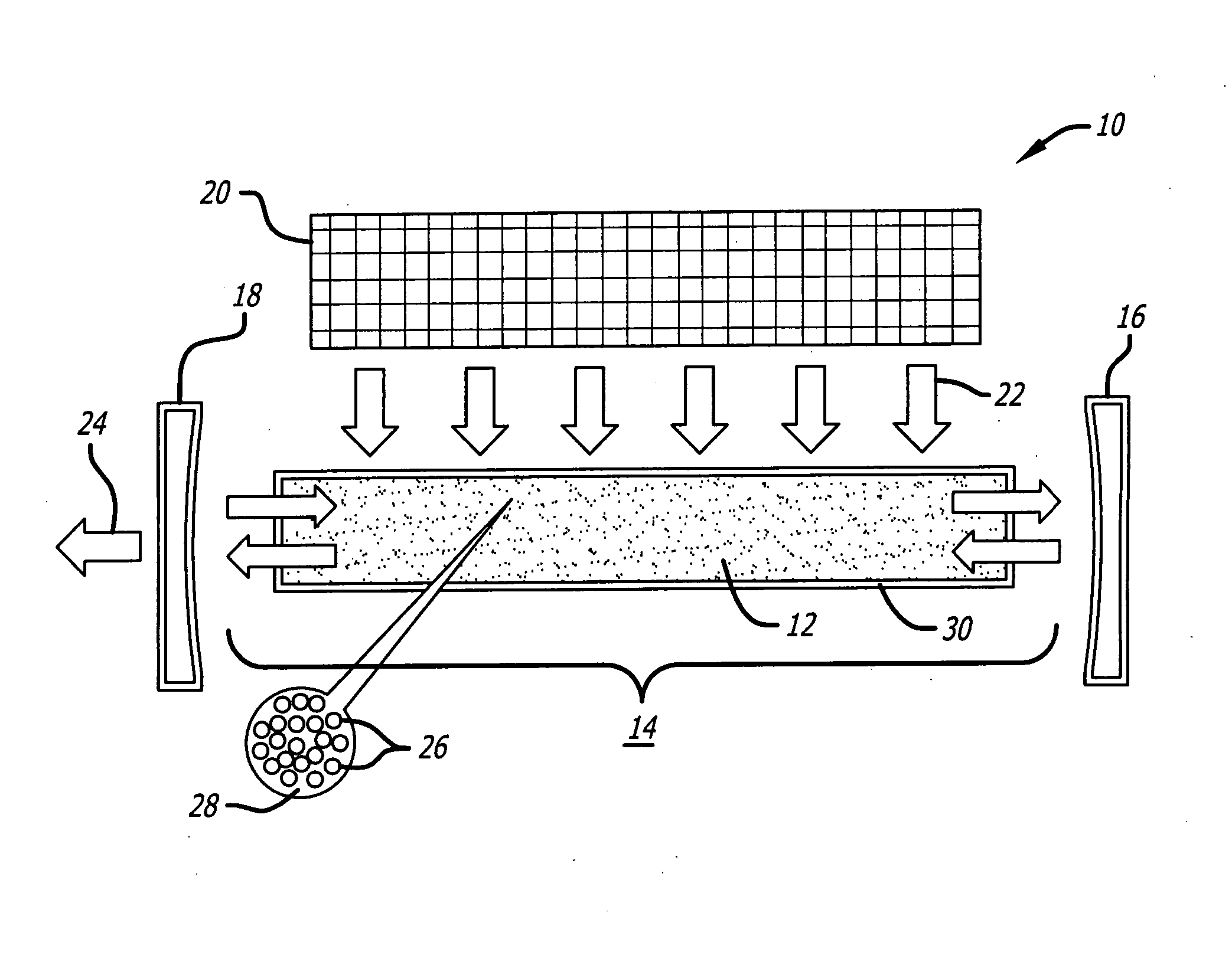
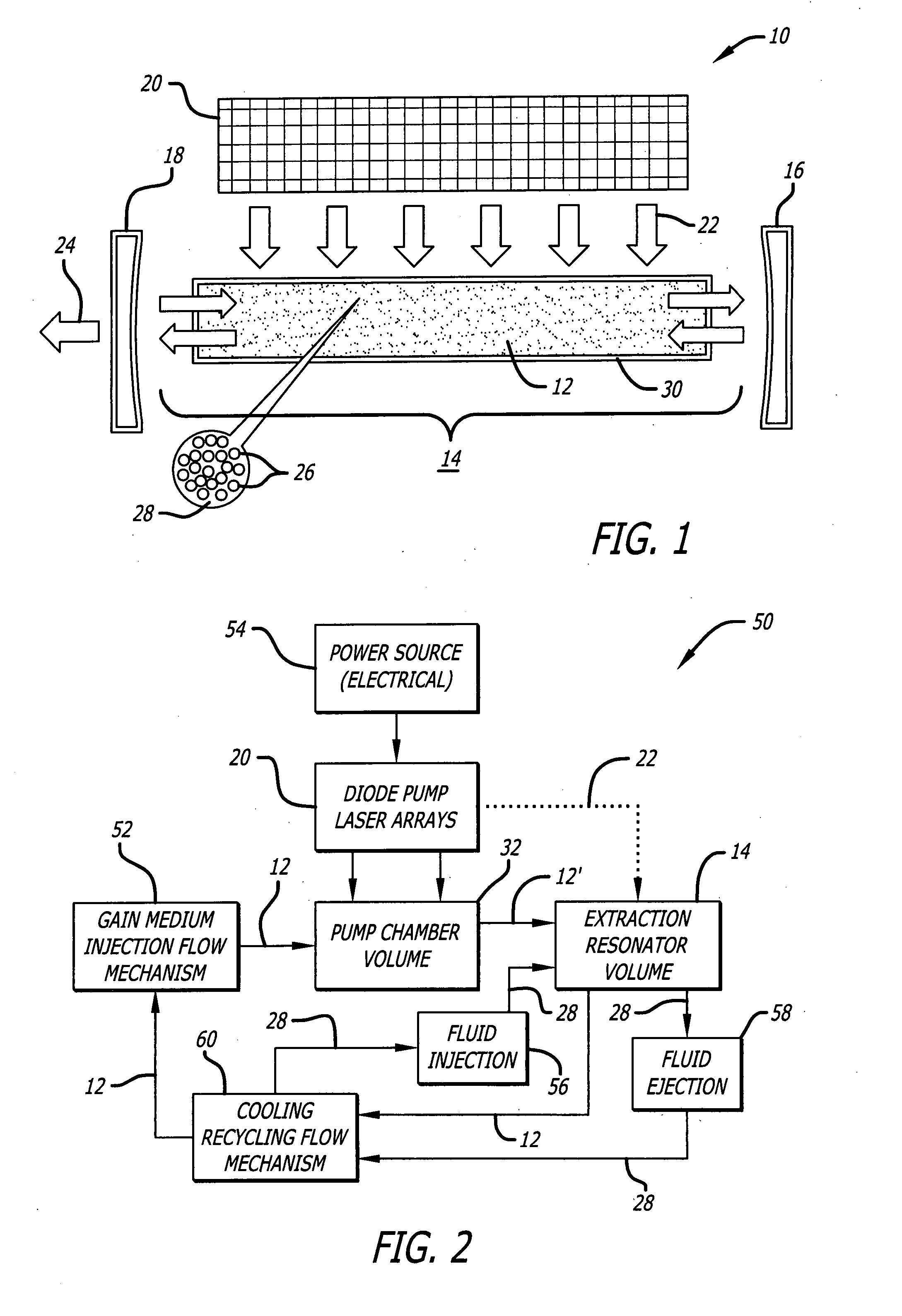
[0022] As is well known in the art, a laser typically includes a gain medium disposed in a resonator, and a pump source. The gain medium is excited to a higher energy state by the pump source, and the resultant emitted fight is bounced back and forth within the resonator, triggering further stimulated emissions. The laser gain medium can be a sol...


PUM


Abstract

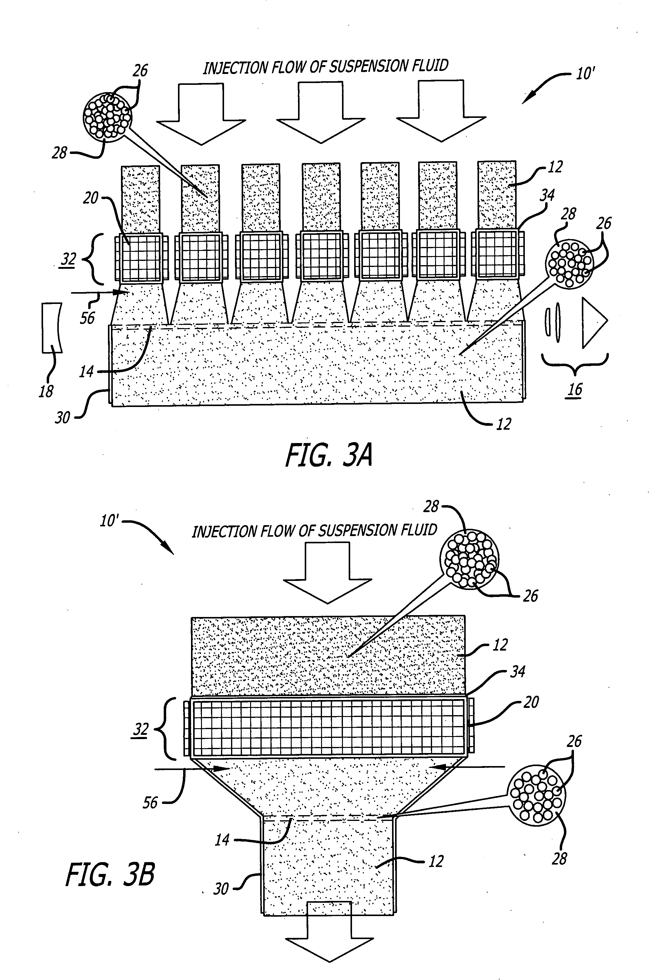
A laser. The novel laser includes a gain medium, a pump source adapted to optically excite the gain medium in a first location, and a resonator adapted to extract energy from the gain medium in a second location distinct from the first location. In an illustrative embodiment, the gain medium is comprised of a plurality of solid-state gain particles suspended in a fluid. The gain medium is adapted to flow, and optical excitation of the gain medium occurs outside of the resonator. In a preferred embodiment, the flow velocity and the density of gain particles in the gain medium are adjusted for optimal absorption efficiency during optical excitation and then for optimal extraction efficiency in the resonator. In addition, the resonator may be shaped for optimal extraction efficiency, while pump modules that hold the gain medium during optical excitation are shaped for optimal absorption efficiency.

Description

REFERENCE TO RELATED APPLICATION [0001] This Application is a Divisional of U.S. patent application Ser. No. 10 / 915,229, entitled SOLID-STATE SUSPENSION LASER filed Aug. 10, 2004 by Alexander A. Betin et al., the teachings of which are incorporated herein by reference.BACKGROUND OF THE INVENTION [0002] 1. Field of the Invention: [0003] The present invention relates to optical systems. More specifically, the present invention relates to solid-state lasers. [0004] 2. Description of the Related Art [0005] Weapon-class lasers are required to have the highest possible power per weight ratio in order to fulfill requirements for a variety of airborne and ground tactical applications. The implementation of a high-energy weapon-class laser system is currently limited to large platforms due to the relatively low power per weight ratio numbers in the present approaches. [0006] Prior attempts to implement a weapons class laser range from the chemical laser to the diode-pumped solid-state power ...

Claims


Application Information

Patent Timeline
Patent Type & Authority Applications(United States)
IPC IPC(8): H01S3/20H01S3/14
CPCH01S3/02H01S3/0602H01S3/20H01S3/1603H01S3/169H01S3/0612
Inventor BETIN, ALEXANDER A.SPARIOSU, KALIN
Owner OL SECURITY LIABILITY CO
Learn More