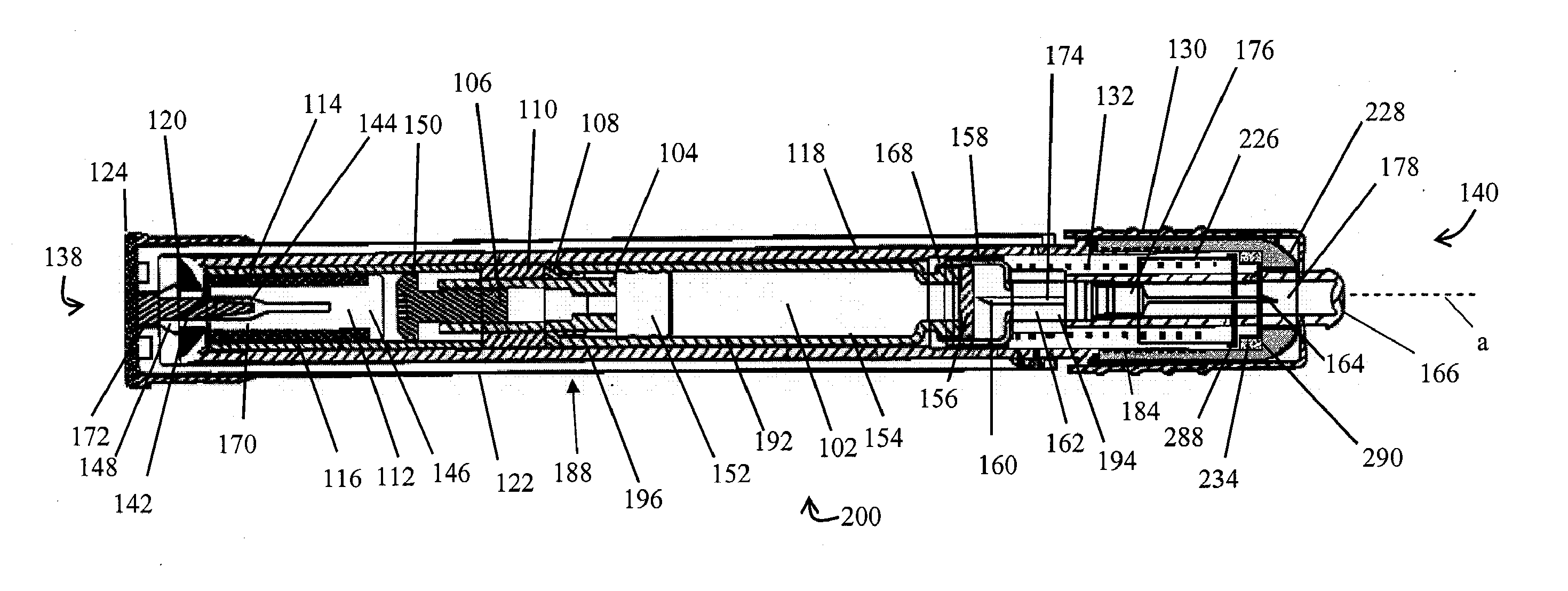
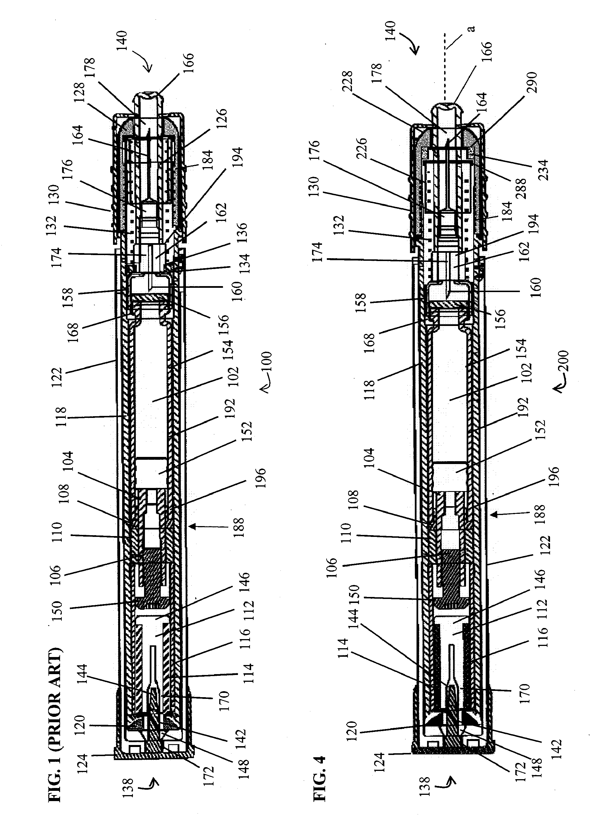
[0089] Also depicted in FIG. 8 are parts of the injection needle 164 and the hub
nose 176, as well as the return spring 132. Again, as the shock absorber 234 of the invention is not required to move with the needle hub 194 during firing in preferred embodiments, it can be made larger in any dimension, and thus of greater
damping capacity, than the prior art shock absorber. Also, although operation of the depicted device would not generally be impeded by inclusion of a shock absorber modifier between the
needle penetration controller 226 and the needle hub 294 (or for that matter between the
needle penetration controller 226 and the shock absorber 234), it is an
advantage of the invention that no such modifier is necessary for proper operation of the shock absorber system 300 of the invention.
[0090] Thus, an automatic injector device of the invention in certain embodiments comprises a housing, a firing spring within the housing, a
syringe assembly containing the medicament adjacent the firing spring, and a shock absorber adapted to absorb excess
dynamic energy that is left over after the medicament has been injected into the patient. In certain embodiments of the invention, the shock absorber is located within a removable
nose cone that fits over the end of the housing. In particular embodiments, the shock absorber is located on a shelf within the removable
nose cone.
[0091] Thus, the invention provides an improved shock absorber system for an automatic injector, including a dual-use or multi-use automatic injector, as described herein. The improved shock absorber provides exceptional
energy management, reducing dynamic stresses on internal components of the automatic injector during firing. In particular, the shock absorber system includes a stationary shock absorber, especially a stationary shock absorber located between the
syringe and the
muzzle end of the automatic injector. Moreover, in using a stationary shock absorber, the improved shock absorber system does not require, and in particular embodiments does not employ, a shock absorber that is located on or that travels with the
syringe during firing of the automatic injector. Additionally, the improved shock absorber system does not require, and in particular embodiments specifically does not include a shock absorber modifier. More particularly, the improved shock absorber system does not require, and in specific embodiments does not include, a shock absorber modifier that is located on or that moves with the syringe during firing of the automatic injector. Thus, specific embodiments of the invention provide an automatic injector having a stationary shock absorber, but excluding a shock absorber, a shock absorber modifier or both a shock absorber and a shock absorber modifier that are on the syringe or travel with the syringe during firing of the automatic injector.
[0092] A firing spring according to the invention includes a spring designed to deliver the necessary force to move the syringe
assembly (including the needle) down the
barrel, push the needle into the patient, activate the hub and deliver the medicament to the patient through the needle.
[0093] In order to perform all the necessary functions during firing of the automatic injector, i.e. moving the syringe down the injector
barrel, inserting the needle into the patient, activating the hub and injecting the medicament into the patient, the firing spring must, when compressed, be adapted to release sufficient energy to complete each of these actions. In general, it is advantageous to provide a spring capable of delivering
excess energy in order for the device to operate under a range of operational conditions. Provision of excess
potential energy in the spring ensures that, at each step in firing of the automatic injector, there will be adequate dynamic
spring force to carry out that step throughout a range of ambient conditions. By providing enhanced management of dynamic forces within the automatic injector during firing, the improved shock absorber according to the invention supports use of springs capable of releasing greater amounts of energy than were supported by the prior art shock absorber. Thus, the improved shock absorber of the invention reduces stresses on internal components of the automatic injector during firing.
[0094] The spring rate (K) of a spring is the amount static
spring force (expressed in 1 lb·f or lbs) per unit length of compression (measured in inches). Thus, the spring rate (K) is expressed in lbs / in. In some embodiments of the invention, the automatic injector comprises a spring having a spring rate (K) in the range of about 6 to about 30 lbs / in, e.g. in the range of about 7.0 to about 20 lbs / in, especially in the range of about 7.5 to about 15 lbs / in, especially about 5, about 6, about 7, about 8, about 9, about 10, about 11 or about 12 lbs / in.


