Wall Exterior Structure for Outer Wall Heat-Insulated Building and Wall Exterior Base, Lateral Furring Frame for Wall Exterior Material Installation and Method for Covering Wall Using Lateral Furring Frame, and Exterior Base Material and Outer Wall Using Exterior Base Material

Inactive Publication Date: 2007-09-27
OMIYA KENJI
View PDF0 Cites 21 Cited by
  • Summary
  • Abstract
  • Description
  • Claims
  • Application Information

AI Technical Summary

Benefits of technology

[0056] According to the outer wall using wall exterior base for an outer wall heat insulated building (defined in claims 26 to 27), an outer exterior base use

Problems solved by technology

However, the conventional structure requires attachment of spacers onto exterior surfaces of an outer wall acting as a structural frame and formation of foamed outer heat insulation layers at the construction site.
Therefore, undesired problem is that the heat insulation external work on the construction spot is complicated and much hours of work are consumed.
As a result, it is unavoidable that a failure such as deflection of mounting shafts of the fittings may be induced.
However, the total dimension between the surface of the exterior portion and each furring step is generally limited to about 7 cm.
More increasing the total dimension leads to excessively lengthening the effective shaft length of the fixing tool.
The increased dimension leads to easily deflecting the shaft and decreasing the overall strength, a

Method used


Image

  • Wall Exterior Structure for Outer Wall Heat-Insulated Building and Wall Exterior Base, Lateral Furring Frame for Wall Exterior Material Installation and Method for Covering Wall Using Lateral Furring Frame, and Exterior Base Material and Outer Wall Using Exterior Base Material
  • Wall Exterior Structure for Outer Wall Heat-Insulated Building and Wall Exterior Base, Lateral Furring Frame for Wall Exterior Material Installation and Method for Covering Wall Using Lateral Furring Frame, and Exterior Base Material and Outer Wall Using Exterior Base Material
  • Wall Exterior Structure for Outer Wall Heat-Insulated Building and Wall Exterior Base, Lateral Furring Frame for Wall Exterior Material Installation and Method for Covering Wall Using Lateral Furring Frame, and Exterior Base Material and Outer Wall Using Exterior Base Material

Examples


embodiment 1

[0128] First, according to the first embodiment, a wall exterior structure and a wall exterior base, shown in FIGS. 1 to 12, will be explained below.

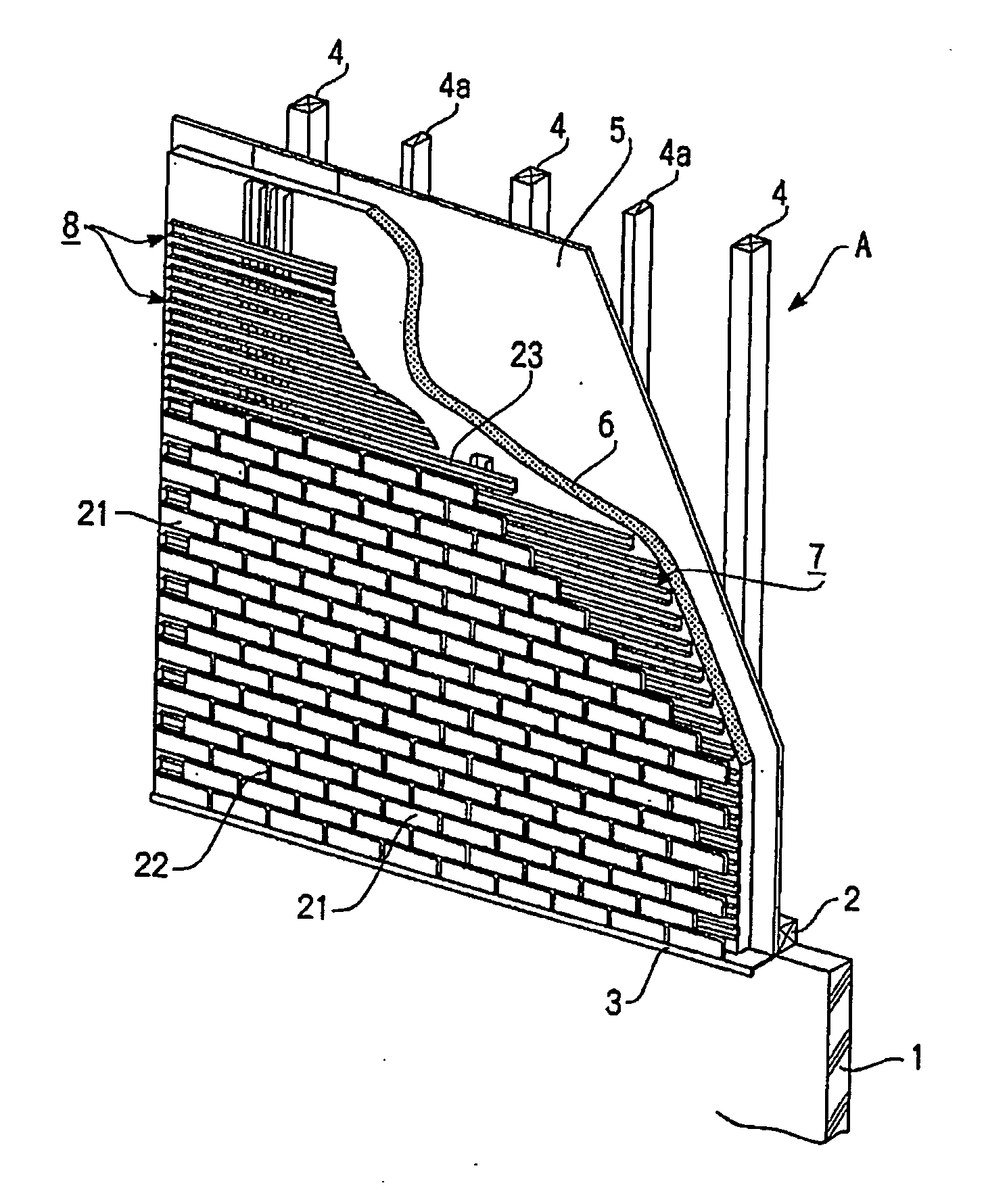
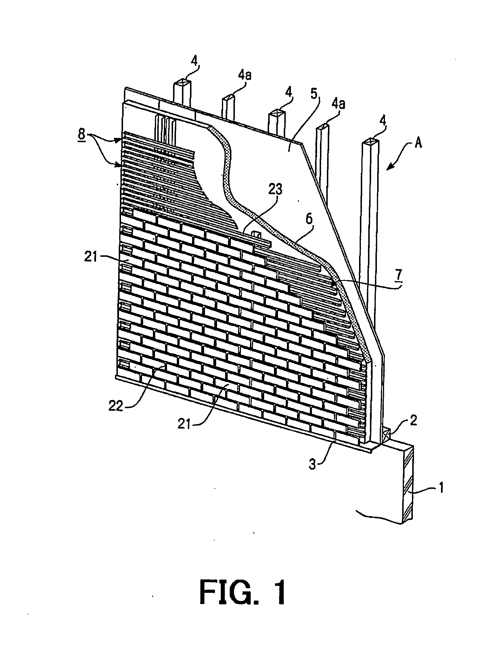
[0129] FIGS. 1 to 12 show various elements in an outer wall heat insulated building according to the first embodiment. FIG. 1 shows a single family house to which an outer wall portion A is heat insulated according to the wooden axial assembling construction method. The single family house includes a structural base 1 having its lower side embedded in the ground, a basic frame 2 fixed on the structural base 1 and from which a weather board 3 is extended out under a heat insulation structure, and plural main columns 4 and plural studs 4a planted on the basic frame 2.

[0130] The outer wall portion A is formed of a structural panel 5 (being a structural frame in a broader sense) overlying a required surface between the main column 4 and the stud 4a and an outer heat insulation layer 6 disposed over the structural panel 5. An exterior base...

second embodiment

[0153] Next, a wall exterior structure embedding the second embodiment of the present invention and a lateral furring strip for wall exterior including the wall exterior base will be explained by referring to FIG. 13 to FIG. 35.

[0154] The second embodiment belongs to the same line as the first embodiment and has so much in common with the first embodiment. Hence, the explanation becomes complicated. In the second embodiments shown in FIGS. 13 to 35, like numerals are attached to the same elements as those in the first embodiment. Thus, the explanation is simplified. The number of 100 is added to the corresponding numerals of main elements.

[0155] In the third embodiment, like numerals are attached to the same elements as elements in the first and third embodiments and the explanation is simplified. The number of 200 is added to the corresponding numerals of main elements.

[0156] In the second embodiment shows FIGS. 13 to 35, a metallic lateral furring strip frame 100a is formed of ...

third embodiment

[0160] Next, a wall exterior structure according to the third embodiment of the present invention and a wall exterior base thereof will be explained by referring to FIGS. 36 to 50.

[0161] In the third embodiment shows in FIGS. 36 to 50, a metallic rail unit frame 200a is formed of fourth vertical rails (vertical furring strips) 201 (hereinafter merely referred to as “vertical rails 201”), plural third standard lateral rails for unit formation (unit formation standard lateral furring strips) 202 (hereinafter merely referred to as “standard lateral furring strips 202 for unit formation”), plural third bridge short lateral rails (short lateral furring strips for bridging) (hereinafter merely referred to as “short lateral rails 203 for bridging), and plural third extension adjustment lateral rails (lateral furring strips for extension adjustment) 204 (merely referred to as “lateral rails 204 for extension adjustment”). Each fourth vertical rail 201 corresponds to the vertical furring st...


PUM


Abstract

In a wall exterior structure, an exterior base is formed of a number of vertical furring strips and a number of lateral furring strips, which are arranged in lattice to each other, each furring strip being a C-shaped channel material. A latch tongue, formed to an upright piece of each vertical furring strip, is latched to an upper through hole in each lateral furring strip. The upright piece is disposed at the position where a vertical furring strip intersects a lateral furring strip. The exterior base is provided by fixing the vertical furring strips on the surface of an outer heat insulating layer. An exterior material is hung to the exterior base so that an outer wall is made through a simple work. A ventilation space of about 5 mm, depending on the thickness of the vertical furring strip, is defined outside the outer heat insulating layer. The ventilation space is generally about 2 cm in thick. Hence, the reduced ventilation space can improve the heat insulation property of a building.

Description

TECHNICAL FIELD [0001] The present invention relates to a wall exterior structure for an outer wall heat-insulated building and to a wall exterior base. Furthermore, the present invention relates to a lateral furring frame for wall exterior material installation and to a method for covering walls using the lateral furring frame. Moreover, the present invention relates to an exterior base material and to an outer wall using the exterior base material. [0002] In more detail, the present invention is made to mount a surface exterior portion to an outer wall via an outer heat insulated layer in a building such as a single-family house. For that purpose, the present invention relates to improving (1) a wall exterior structure and a base for the wall exterior, (2) a lateral furring frame for wall exterior material installation (metallic lateral furring frame) and a method for covering a wall surface using the lateral furring frame, and (3) an exterior base material and outer wall using th...

Claims


Application Information

Patent Timeline
IPC IPC(8): E04F13/00E04B2/56E04F13/08
CPCE04F13/0862E04F13/0826E04F13/08
Inventor OMIYA, KENJI
Owner OMIYA KENJI
Why Eureka
Try Eureka