Systems and methods for low-temperature gas separation

a low-temperature gas and gas separation technology, applied in the direction of separation processes, liquefaction, lighting and heating apparatus, etc., can solve the problems of high energy consumption and significant mixture pressure loss in the low-temperature separation process

Inactive Publication Date: 2007-10-04
3S GAS TECH LTD
View PDF99 Cites 42 Cited by
  • Summary
  • Abstract
  • Description
  • Claims
  • Application Information

AI Technical Summary

Benefits of technology

[0008] According to an aspect of an embodiment of the invention there is provided a method of low-temperature gas mixture separation, suitable for separating components of a hydrocarbon gas mixture, including: cooling a gas mixture; condensing a gas mixture to produce a liquid stream and a gas / vapor; rectifying at least a portion of the liquid stream thereby producing respective gas-phase products; transferring heat energy to or from at least one of the liquid stream, the gas / vapor stream and gas-phase products from or to at least another one of the gas mixture, the liquid stream, the gas / vapor stream, gas-phase products and another flow in order to recycle energy.

Problems solved by technology

The essential drawbacks of these methods of low temperature gas separation are the significant mixture pressure losses in the low temperature separation process and high energy consumption.

Method used


Image

  • Systems and methods for low-temperature gas separation
  • Systems and methods for low-temperature gas separation
  • Systems and methods for low-temperature gas separation

Examples


first embodiment

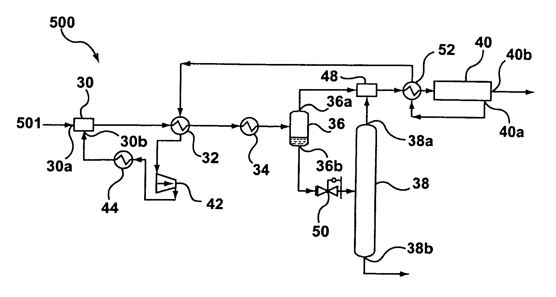
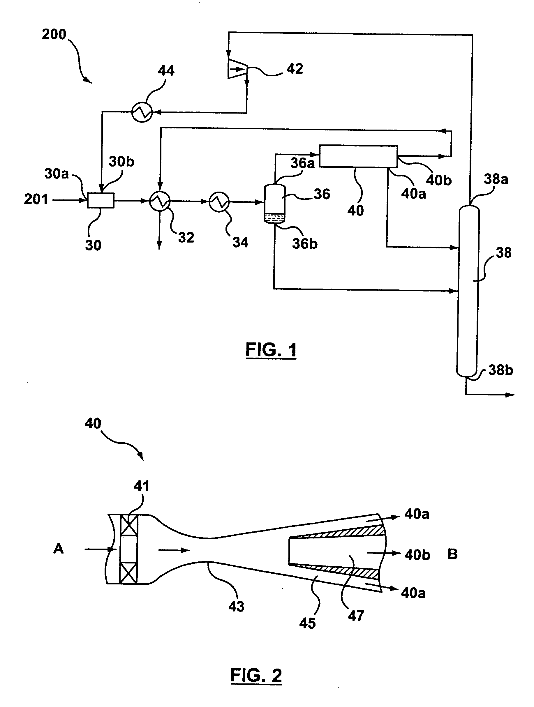
[0074] Referring to FIG. 1, shown is a schematic drawing of a low-temperature gas mixture separation system 200 according to the invention, referred to as the system 200 hereinafter for brevity. Those skilled in the art will appreciate that the system 200 includes a suitable combination of associated structural elements, mechanical systems, hardware, firmware and software that is employed to support the function and operation of the system 200; however, the system 200 is illustrated showing only those elements necessary to describe aspects of this embodiment.

[0075] The system 200 includes a first mixer 30, a first heat-exchanger 32, a first chiller 34 and a gas / liquid separator 36 connected respectively in series. The first mixer 30 includes respective first and second inputs 30a and 30b. The first input 30a serves as an input to the system 200 as a whole as well as an input of the first mixer 30. The second input 30b serves a feedback input, the purpose of which is described in mor...

second embodiment

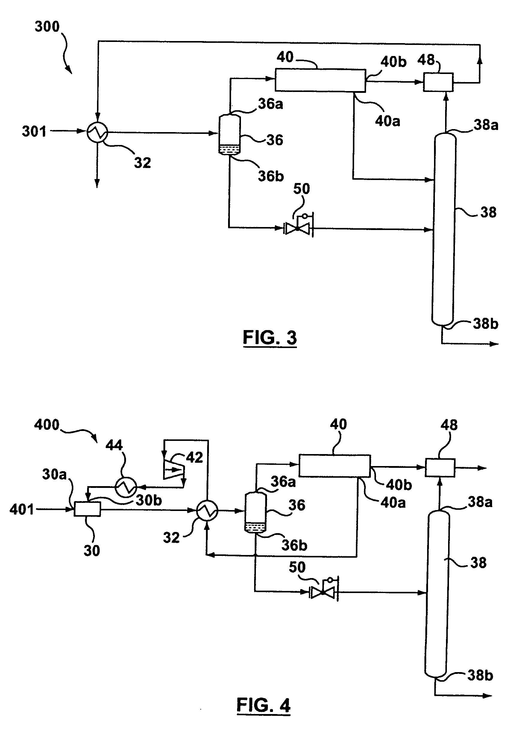
[0087] Referring to FIG. 3, shown is a schematic drawing of a low-temperature gas mixture separation system 300 according to the invention, referred to as the system 300 hereinafter for brevity. The system 300 illustrated in FIG. 3 is similar to the system 200 illustrated in FIG. 1, and accordingly, elements common to both share common reference numerals. Moreover, for the sake of brevity, portions of the description of FIG. 1 will not be repeated with respect to FIG. 3. Again those skilled in the art will appreciate that the system 300 includes a suitable combination of associated structural elements, mechanical systems, hardware, firmware and software that is employed to support the function and operation of the system 300; however, the system 300 is illustrated showing only those elements necessary to describe aspects of this embodiment of the invention.

[0088] The differences between the systems 200 and 300 are as follows. The system 300 does not include the first mixer 30, the f...

third embodiment

[0091] Referring to FIG. 4, shown is a schematic drawing of a low-temperature gas mixture separation system 400 according to the invention, referred to as the system 400 hereinafter for brevity. The system 400 illustrated in FIG. 4 is similar to the respective systems illustrated in FIGS. 1 and 3, and accordingly, elements common to each share common reference numerals. Moreover, for the sake of brevity, portions of the descriptions for FIGS. 1 and 3 will not be repeated with respect to FIG. 4. Those skilled in the art will appreciate that the system 400 includes a suitable combination of associated structural elements, mechanical systems, hardware, firmware and software that is employed to support the function and operation of the system 400; however, the system 400 is illustrated showing only those elements necessary to describe aspects of this embodiment of the invention.

[0092] The arrangements specifically shown with respect to the system 400 are as follows. The system 400 inclu...


PUM

PropertyMeasurementUnit
temperatureaaaaaaaaaa
heat energyaaaaaaaaaa
heataaaaaaaaaa

Abstract

One of the drawbacks common to many currently available low-temperature gas mixture separation techniques is that known systems and methods that embody the techniques are inefficient. In contrast to known systems and methods for low-temperature gas mixture separation, some embodiments of the present invention provide a system for low-temperature gas mixture separation that recycles energy and reduces power consumption by re-circulating heated and/or cooled flows (e.g. gas, liquid and mixed-phase flows) within the system. Accordingly, in some embodiments efficiency is somewhat improved, as compared to comparable systems that do not include the re-circulation of heat energy. In some embodiments the heat energy that is re-circulated is a combination of heat added to the system (i.e. inputs to the system) and heat released within the system (i.e. byproducts from within the system) that are subsequently recovered. In particular, some systems and methods provided in accordance with embodiments of the invention are suited for separating the constituent components of natural gas and other hydrocarbon gas mixtures.

Description

PRIORITY CLAIM [0001] This application claims the benefit of Russian Patent Application No. 2004128348 / 06 (030834), filed on Sep. 24, 2004, and the entire content of which is hereby incorporated by reference. FIELD OF THE INVENTION [0002] The invention relates to gas separation techniques, and in particular to systems and methods for low-temperature gas separation. BACKGROUND OF THE INVENTION [0003] Existing processes of low temperature separation of the aimed components from the gas mixtures are based on the gas mixtures chilling, aim components condensation and subsequent separation of the condensate, containing the aimed components, from the gas mixture. At this the chilling of a gas mixture is conventionally performed either at the expense of gas expansion in the throttles and expanders or the application of chilling devices. As additional auxiliary equipment recuperative heat exchangers and rectifying towers are used in the schemes of low temperature gas separation. [0004] The ...

Claims


Application Information

Patent Timeline
Patent Type & Authority Applications(United States)
IPC IPC(8): F25J3/00
CPCB01D5/0033F25J2270/90F25J3/0209F25J3/0233F25J3/0238F25J2200/02F25J2200/70F25J2200/76F25J2205/04F25J2205/10F25J2210/04F25J2230/08F25J2230/60F25J2240/02F25J2240/60F25J2245/02F25J2270/02F25J2270/04B01D5/0045F25J2270/88B01D3/00B01D5/00C10G7/00F25J3/02
Inventor ALFEROV, VADIM IVANOVICHBAGIROV, LEV ARKAD'EVICHFEYGIN, VLADIMIR ISAAKOVICHIMAEV, SALAVAT ZAINETDINOVICHDMITRIEV, LEONARD MAKAROVICH
Owner 3S GAS TECH LTD
Why Eureka
Try Eureka