Coil apparatus and nuclear magnetic resonance apparatus using the same

a technology of nuclear magnetic resonance and coil, applied in the field of coil, can solve the problems of reducing the productivity of coils, increasing the loss, and prolonging the irradiation time, and achieve the effect of large degree of freedom in design and simple configuration

Inactive Publication Date: 2007-10-04
HITACHI LTD
View PDF13 Cites 15 Cited by
  • Summary
  • Abstract
  • Description
  • Claims
  • Application Information

AI Technical Summary

Benefits of technology

[0011] Another object of the present invention is to provide a coil apparatus suitable for an MRI apparatus, especially for a high magnetic field MRI apparatus, and provide a coil apparatus that can cope with both the parallel imaging and parallel transmission.
[0015] The coil apparatus according to the present invention can be combined with a measurement apparatus in which the number of the reception means or transmission means in transmission and reception means is less than the number of subcoils. For example, each of a plurality of subcoils is connected to transmission means, and only one subcoil is connected to reception means. Or each of the subcoils is connected to reception means, and only one subcoil is connected to transmission means. As a result, the multi-channel transmission / one-channel reception or the one-channel transmission / multi-channel reception can be implemented without increasing the number of the transmission coils or reception coils.
[0016] In the coil apparatus according to the present invention, the coil conduction means can include second conduction control means for controlling a conduction state between the subcoils. Owing to this configuration, it becomes possible to facilitate the circuit design of the first conduction control means and implementation of the one-channel transmission / multi-channel reception.
[0018] In accordance with an aspect of the coil apparatus according to the present invention, subcoils disposed so as to be adjacent to each other have an electromagnetic wave transmission property between. As a result, it becomes possible to use the coil apparatus according to the present invention together with another transmission coil disposed on the outside of the coil apparatus according to the present invention.
[0020] In addition, the present invention provides an MRI apparatus including the above-described coil apparatus. By including this coil apparatus, it is possible to implement parallel transmission utilizing the multi-channel transmission / one-channel reception and parallel imaging utilizing the one-channel transmission / multi-channel reception with a comparatively simple configuration.
[0021] According to the present invention, a microstrip line type coil and a multiple patch resonator type coil having a large degree of freedom in design when using a high magnetic field MRI apparatus, can be implemented by using one coil. Furthermore, since the coil has a form that allows intrusion of an external RF electromagnetic field when the coil is made to operate as a one-channel coil of multiple patch resonator type, it is also possible to use the coil as a dedicated reception coil and conduct the RF transmission by using a different external large coil.

Problems solved by technology

On the other hand, a higher magnetic field in the MRI apparatus causes new problems such as uneven current distribution in the RF coil, a loss increase caused by higher resistance in the RF coil, uneven excitation region caused by RF absorption in the human body, and lowering in coil productivity caused by a limit of the self-resonant frequency in the RF coil.
In this method, however, there is a problem that the irradiation time becomes longer.
It requires some cost to prepare the multi-channel receiver.
However, the coil of this type cannot cope with the multi-channel transmission and the multi-channel reception.
When the number of channels increases, however, there is a demerit that the circuit adjustment and the work of balancing the compounding conducted among channels become complicated.
Even if this technique is used, however, adaptation to the multi-channel transmission / one-channel reception is difficult.
Furthermore, since the reception coil scheme is a loop coil array, coupling between adjacent coils increases, resulting in a demerit that the mounting becomes difficult and the configuration becomes complicated.
Furthermore, in this method, nothing but a multi-channel configuration of N / 2 channels can be implemented, where N is the number of conductors in a multiple patch resonator type coil called rung.

Method used


Image

  • Coil apparatus and nuclear magnetic resonance apparatus using the same
  • Coil apparatus and nuclear magnetic resonance apparatus using the same
  • Coil apparatus and nuclear magnetic resonance apparatus using the same

Examples


examples

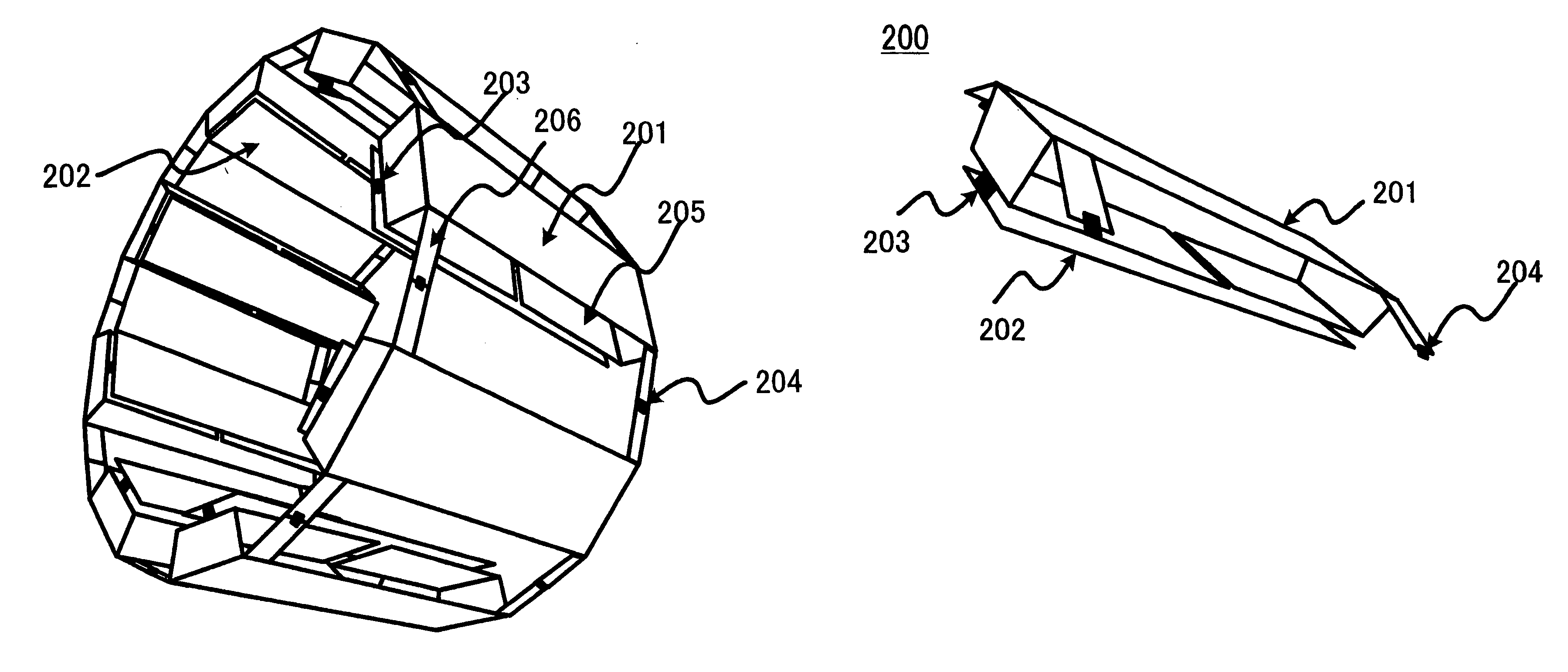
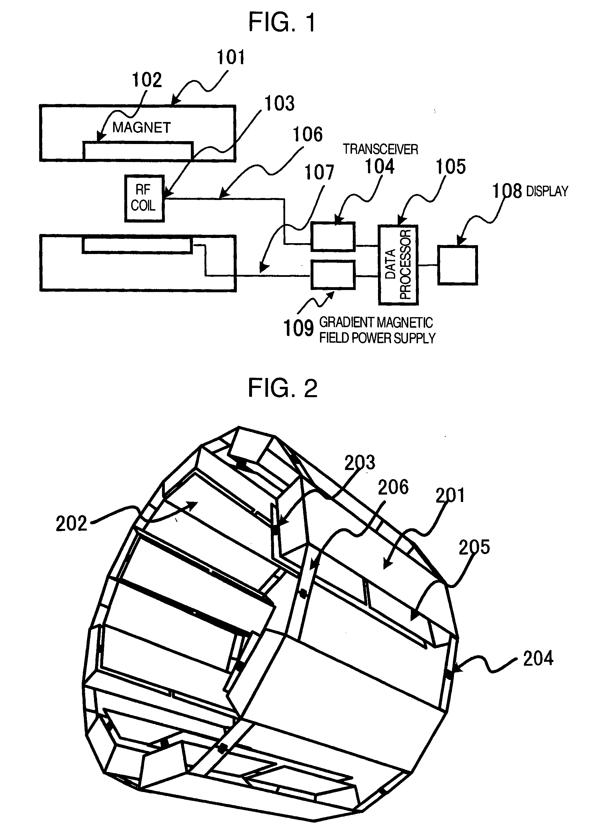
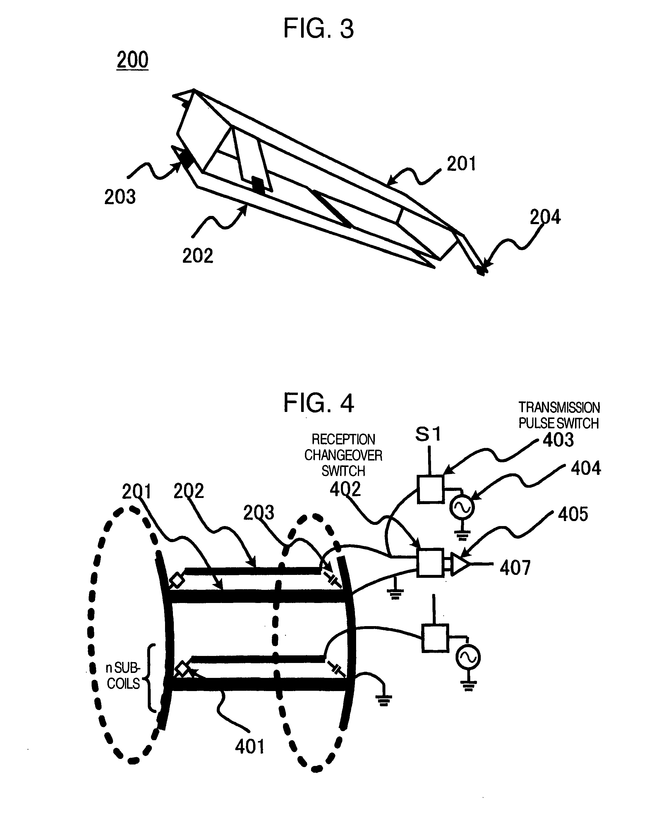
[0074] Hereafter, examples of the case where an RF coil has a shape including eight subcoils as shown in FIG. 2 is applied to the multi-channel transmission / one-channel reception and the one-channel transmission / multi-channel reception will be described. Coil design in the examples described hereafter is based upon results obtained by conducting simulation on an RF coil having a length in the axial direction of approximately 220 mm, an outside diameter of approximately 340 mm, and an inside diameter of approximately 270 mm.

first example

[0075] First, resonance characteristics of an RF coil having a shape including eight subcoils are found by simulation. Results are shown in FIG. 12. In FIG. 12, the abscissa indicates the frequency and the ordinate indicates resonance impedance. As indicated by a graph 601, a plurality of peaks appear in resonance characteristics in the one-channel mode. There is a property that the number of peaks becomes equal to (the number of subcoils / 2+1). In the RF coil including eight subcoils, the number of peaks becomes five. At a resonance peak having a second lowest frequency among five peaks arranged on a frequency axis, the sensitivity is obtained most uniformly within the coil cylinder. In the coil design, therefore, it is necessary to determine the capacitance of the capacitor 203 between conductors and the capacitance of the capacitance changeover capacitor 401 so as to make both the resonance peak 602 in the multi-channel mode and the second resonance peak in the one-channel mode eq...

second example

[0079] In the one-channel transmission / multi-channel reception RF coil shown in FIG. 8, the resonance peak in the multi-channel mode and the second resonance peak in the one-channel mode shown in FIG. 12 are set nearly equal to 126 MHz which is the resonance frequency of hydrogen nuclei in the MRI apparatus of 3 Tesla. In this case, the capacitance of the inter-conductor capacitor 203 and the capacitance of the capacitance changeover capacitor 401 are found by simulation. In the one-channel transmission / multi-channel reception RF coil, the inter-subcoil conduction control circuit 204 is added between the first conductors unlike the multi-channel transmission / one-channel reception RF coil.

[0080] Since the conduction between subcoils is limited by the inter-subcoil conduction control circuit 204, the resonance peak in the case of the multi-channel mode (the case of the single peak 602) shifts to the low frequency side. As a result, it becomes possible in the second example as well to...


PUM


Abstract

An RF coil apparatus suitable for a high magnetic field MRI apparatus includes a plurality of subcoils arranged substantially in a cylindrical form. Each subcoil includes a first conductor part and a second conductor part. The second conductor part is disposed on the inside of a cylinder, i.e., on the test subject side. This coil apparatus includes a conduction part for attaining conduction among the subcoils, and a conduction control part for controlling a conduction state between the first conductor part and the second conductor part, conducting connection to a transmission and reception part which conducts signal transmission and reception with a subcoil, and changing over electric capacitance of the subcoil according to whether to receive or transmit. Function changeover between the multi-channel mode and the one-channel mode is accomplished by conducting connection changeover and electric capacitance changeover.

Description

INCORPORATION BY REFERENCE [0001] The present application claims priority from Japanese application JP2006-102870 filed on Apr. 4, 2006, the content of which is hereby incorporated by reference into this application. BACKGROUND OF THE INVENTION [0002] The present invention relates to a coil apparatus for transmitting / receiving an electromagnetic wave, and a nuclear magnetic resonance imaging apparatus (hereafter referred to as “MRI apparatus”) using the coil apparatus. [0003] The MRI apparatus irradiates a subject disposed in a uniform static magnetic field generated by a magnet, with an electromagnetic field, excites nuclear spins in the subject, then receives a nuclear magnetic resonance signal which is an electromagnetic wave generated by nuclear spins, conducts imaging of the subject. The irradiation with the electromagnetic wave and reception of the nuclear magnetic resonance signal are conducted by an RF coil which transmits or receives an electromagnetic wave having a radio f...

Claims


Application Information

Patent Timeline
Patent Type & Authority Applications(United States)
IPC IPC(8): G01V3/00
CPCG01R33/34046G01R33/3453G01R33/3415
Inventor HABARA, HIDETAOCHI, HISAAKI
Owner HITACHI LTD
Why Eureka
Try Eureka