RFID tag and manufacturing method thereof

a technology of rfid tags and manufacturing methods, which is applied in the direction of loop antennas with ferromagnetic cores, burglar alarm mechanical actuation, instruments, etc., can solve the problems of metal impairing the communication waves of rfid tags, troublesome reading of barcodes, and inability to add new information or update information to barcodes. , to achieve the effect of widening the bandwidth, widening the bandwidth, and high precision

Inactive Publication Date: 2007-10-04
FUJITSU LTD
View PDF8 Cites 111 Cited by
  • Summary
  • Abstract
  • Description
  • Claims
  • Application Information

AI Technical Summary

Benefits of technology

[0027] According to this invention it is possible to provide a RFID tag having a loop antenna that does not require a high amount of precision in the positioning of a film on which an IC chip is mounted when wrapping it around a dielectric material, and to provide the manufacturing method thereof.
[0028] Moreover, according to this invention since loop antenna construction is used, it is possible to provide a small, thin RFID tag that is capable of supplying necessary power even when attached to metal, is capable of transmitting and receiving electromagnetic waves, is capab

Problems solved by technology

However, when reading a barcode in the related barcode processing method, the barcode had to be in contact with the barcode reader, which makes the work of reading barcodes troublesome.
Also, in the prior barcode processing method, there was a problem in that it was not possible to add new information or update information to the barcode itself.
However, when the RFID tag is attached to metal such as steel, the metal impairs the communication waves of the RFID tag, and problems occur such as a decrease in communication distance.
Therefore, it is not possible to supply the necessary power for the IC chip of the RFID tag.
Also, it is not possible to transmit (scatter) electromagnetic waves from the tag antenna toward the reader/writer antenna.
This current image negates the electromagnetic field generated by the dipole antenna current 1, and it is not possible to supply the necessary power to the IC chip of the RFID tag, thus it becomes impossible to transmit electromagnetic waves from the tag antenna t

Method used


Image

  • RFID tag and manufacturing method thereof
  • RFID tag and manufacturing method thereof
  • RFID tag and manufacturing method thereof

Examples


first embodiment

(A) First Embodiment

Construction

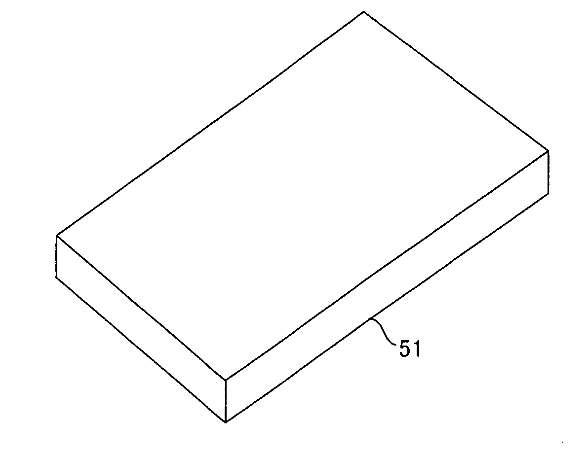
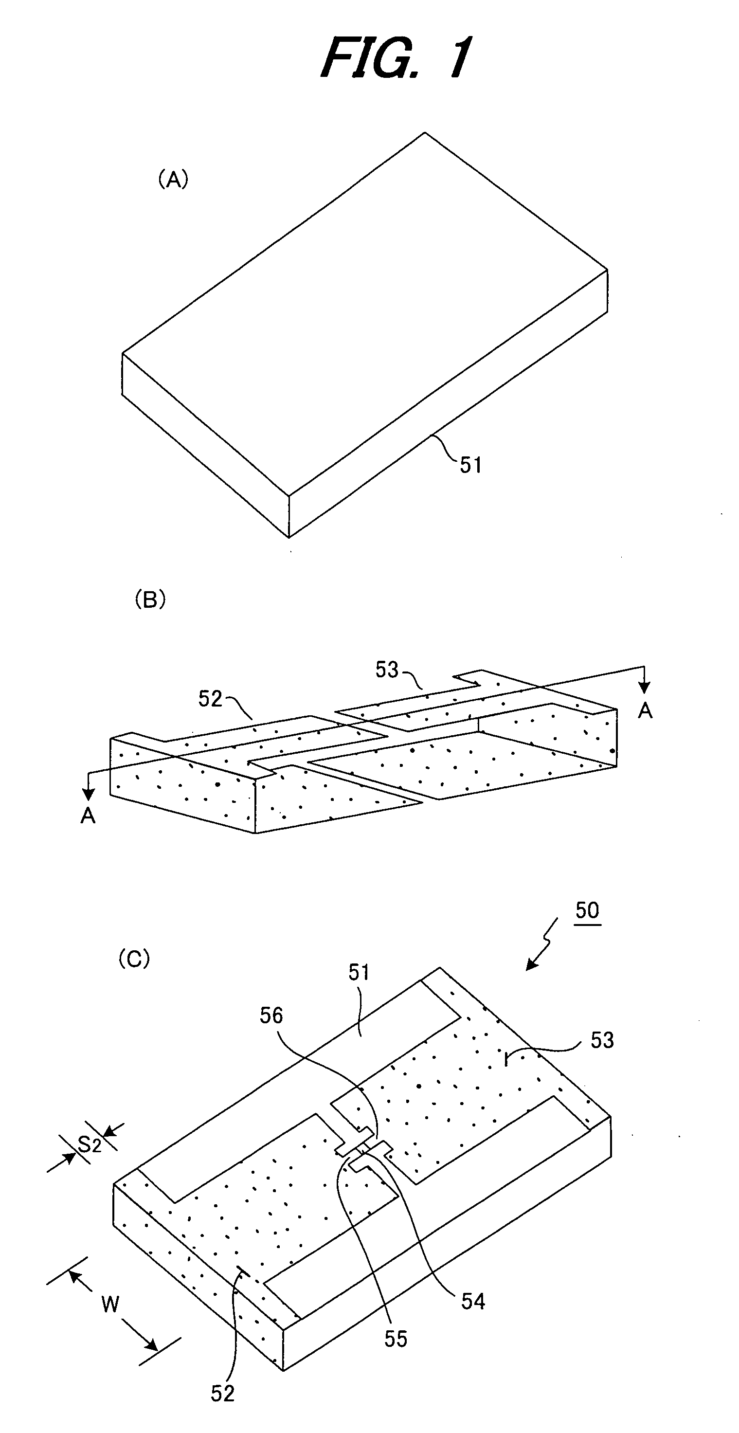
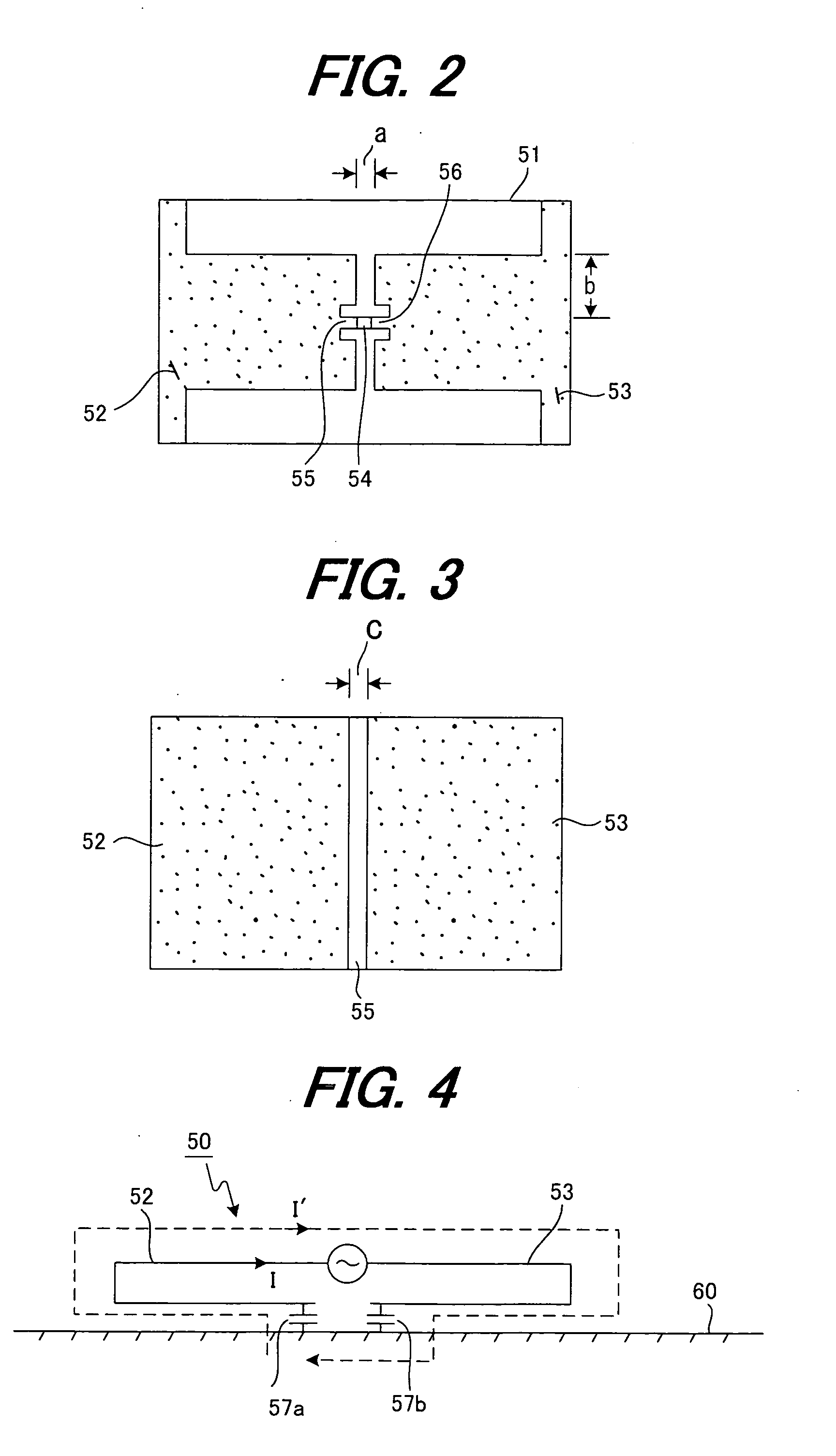
[0054]FIG. 1 is a perspective drawing of details of a RFID tag 50 having the loop antenna construction of this invention. As shown in (A)-(C) of FIG. 1, first and second loop antenna sections 52, 53 having a U-shaped cross section AA are attached to a 78×45×1.2 mm flat plate-shaped dielectric member (dielectric board) 51. Also, a LSI chip 54 is mounted on chip-mounting pads 55, 56 so that it fits in a concave section (not shown in the figure) formed in the dielectric board 51 and so that it is connected to the antenna sections 52, 53. The chip-mounting pads 55, 56 are located on the end sections of the loop antenna sections 52, 53.

[0055] The dielectric board 51, for example has electrical characteristics of a dielectric constant εr=4.3 and dielectric loss factor tan δ=0.009, and can be formed using just inexpensive resin that does not contain glass or the like. For example, this dielectric board 51 can be formed using a resin having good formabilit...

second embodiment

(B) Second Embodiment

[0081] The RFID tag of the first embodiment is attached to a conductive body by way of an insulating layer and used, so an equivalent circuit as shown in FIG. 4 is formed and the required characteristics are obtained. However, in the case of attaching the RFID tag to a non-conductive body, current does not flow through the antenna pattern, so it does not function as a tag antenna.

[0082]FIG. 15 is a drawing explaining the RFID tag having the loop antenna construction of a second embodiment of the invention in which current can flow through the antenna pattern when the RFID tag is attached to a non-conductive body, where (A) of FIG. 15 is an perspective view of details of the RFID tag, and (B) of FIG. 15 is a perspective view of the RFID tag.

[0083] The RFID tag of this second embodiment is constructed with a 100 μm insulating sheet 81 and conductive sheet 82 layered on the bottom surface of the RFID tag 50 (see (C) of FIG. 1) of the first embodiment. By using th...


PUM


Abstract

A RFID tag having a loop antenna comprises: a flat plate shaped dielectric member 51; first and second loop antenna patterns 52, 53 that are formed on a first and second surface of the dielectric member 51 so that they are separated from each other by a specified space, and so that each is continuous from the first surface to the second surface of the dielectric member 51; and an IC chip 54 that electrically connects the first and second loop antenna patterns 52, 53 on one of the surfaces.

Description

BACKGROUND OF THE INVENTION [0001] The present invention relates to a RFID tag and manufacturing method thereof, and particularly to a RFID tag comprising a loop antenna and manufacturing method thereof, and takes advantage of characteristics as a tag antenna even when attached to a conductive body or non-conductive body. [0002] Conventionally, in the distribution industry, the express business industry and the like, a method of printing or attaching a barcode to a product itself or to the product packaging, and reading the barcode with a barcode reader has been widely used as a method for managing individual product information. However, when reading a barcode in the related barcode processing method, the barcode had to be in contact with the barcode reader, which makes the work of reading barcodes troublesome. Also, in the prior barcode processing method, there was a problem in that it was not possible to add new information or update information to the barcode itself. [0003] Ther...

Claims


Application Information

Patent Timeline
IPC IPC(8): G08B13/14
CPCG06K19/07786H01Q7/04H01Q7/00H01Q1/22H01Q1/2225G06K19/07
Inventor YAMAGAJO, TAKASHIMANIWA, TORUKAI, MANABU
Owner FUJITSU LTD
Why Eureka
Try Eureka