Sight-line non contact coupled wireless technology

a wireless technology and non-contact technology, applied in the field of control systems, can solve the problems of adding cost and complexity to the manufacturing operation, components that require exhaustive address assignment and management, etc., and achieve the effect of facilitating system-wide adaptability and reducing the cost and complexity of configuration and reconfiguration of control system components

Active Publication Date: 2007-10-04
ROCKWELL AUTOMATION TECH
View PDF14 Cites 36 Cited by
  • Summary
  • Abstract
  • Description
  • Claims
  • Application Information

AI Technical Summary

Benefits of technology

[0007]This novel approach is thus an improvement over the above mentioned conventional systems in which control system cabling had to be physically connected between components of the mobile pallets and the assembly stations, and further provides a significant advance over prior wireless configurations that required control components of the mobile systems to be assigned a unique address for communications purposes. By the present invention, the mobile systems need not have unique addresses, whereby the cost and complexity of configuration and reconfiguration of control system components can be mitigated when the automated process changes, or when pallets are added to or removed from the system. In this respect, the invention employs wireless transport of control-related information but does not require the wireless nodes of the moving systems to have any wireless address or identity, while also avoiding physical connections between stationary and moving systems in automated industrial control applications. At the same time, the invention addresses wireless cross-talk problems with verification and communication security being provided using optical, magnetic, or other non-contacting signaling that can be modulated in certain embodiments so as to confirm that control components associated with a given assembly station are communicating with control devices of the movable system currently at that station.
[0008]In accordance with one or more aspects of the invention, a control system is provided for controlling operation of a movable system. The control system comprises a wireless communications component associated with a stationary system, along with a non-contacting signaling component associated with the stationary system which is operative to transmit or receive a signal in a signal path proximate the stationary system. A control system component associated with the stationary system is operatively coupled with the non-contacting signaling component and with the wireless communications component. The control system component uses the non-contacting signaling system to verify whether the movable system is proximate the stationary system, and uses the wireless communications component to communicate with one or more control system components associated with a particular movable system while the particular movable system is proximate the stationary system. Any type of non-contacting signal or signals may be used to determine whether the movable system is close to the stationary system, such as optical signals, magnetic signals, or any other signal form that can be transmitted along a defined signal path to allow transmission and receipt when a given movable system is within a desired location and which prevents signal transmission and receipt otherwise. The non-contacting signal, moreover, may be modulated in certain preferred embodiments, and such modulated signal can include an identifier unique to a particular stationary or movable system, thereby facilitating verification that a movable system is proximate the stationary system based on responsive wireless acknowledgment or handshaking communications that include the identifier. In some embodiments, the non-contacting signal is generated by the stationary system, and in others, the mobile system can transmit the optical, magnetic, or other non-contacting signal. In addition, the control system component of the stationary system may use the wireless communications to assign an identifier to a particular movable system while the non-contacting signaling link is established, and the movable system may be operative to provide a previously assigned identifier to a stationary system, to thereby facilitate further system-wide adaptability to different manufacturing goals and strategies.

Problems solved by technology

This physical connection and subsequent disconnection, however, is time consuming and adds cost and complexity to the manufacturing operation.
However, many industrial manufacturing sites include many assembly stations or cells located in close proximity to one another, and the pallets are often separated by only short distances as they travel along the assembly path.
Consequently, conventional attempts at utilizing wireless communications for data transfer between industrial control system components in assembly line situations using smart pallets with on-board control elements and stationary assembly cell control components require exhaustive address assignment and management, including reconfiguration of the stationary and moving control devices when a new pallet is introduced into the system or where the system is changed to perform a different function in the manufacturing process.

Method used


Image

  • Sight-line non contact coupled wireless technology
  • Sight-line non contact coupled wireless technology
  • Sight-line non contact coupled wireless technology

Examples


Embodiment Construction

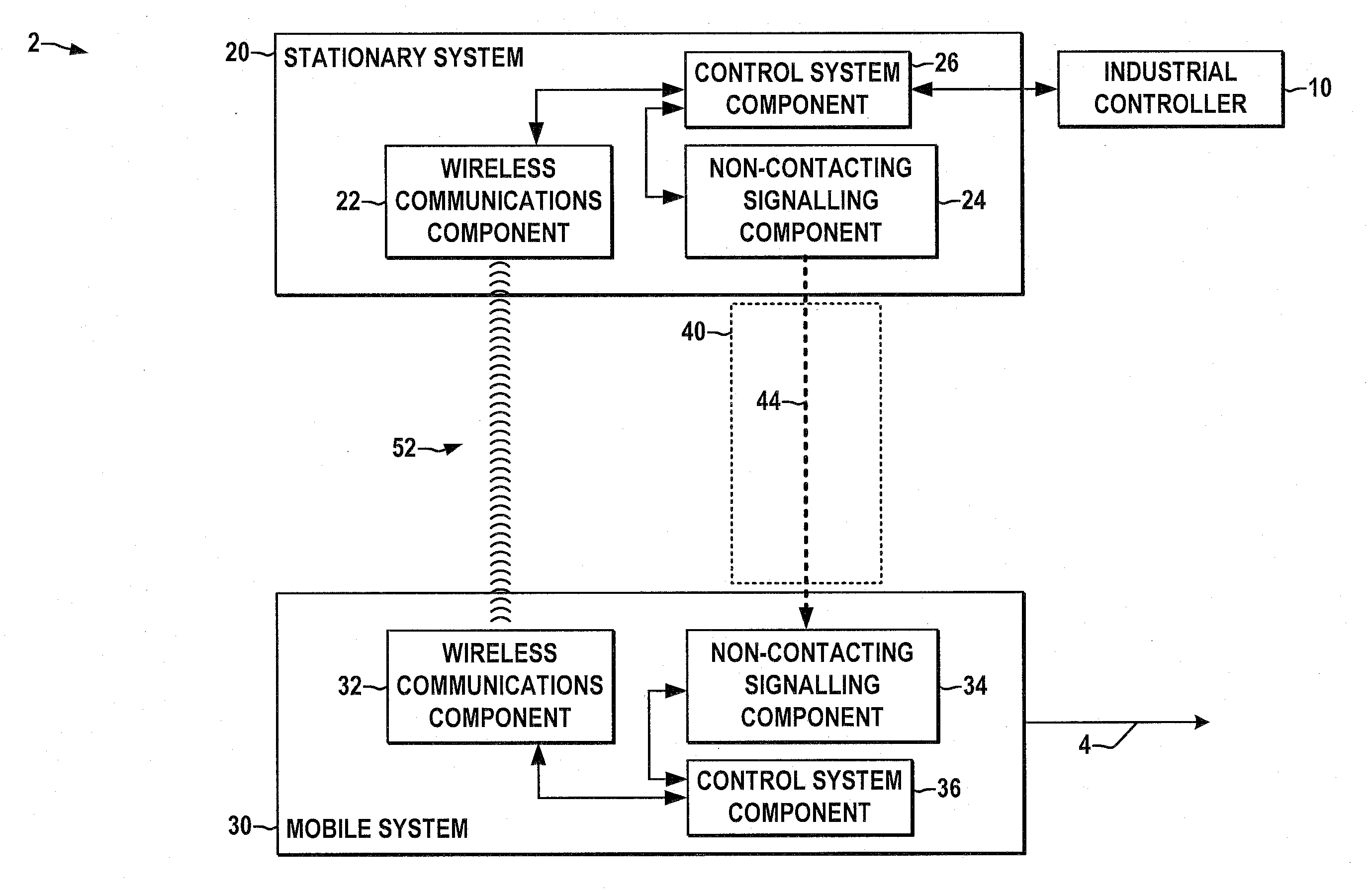
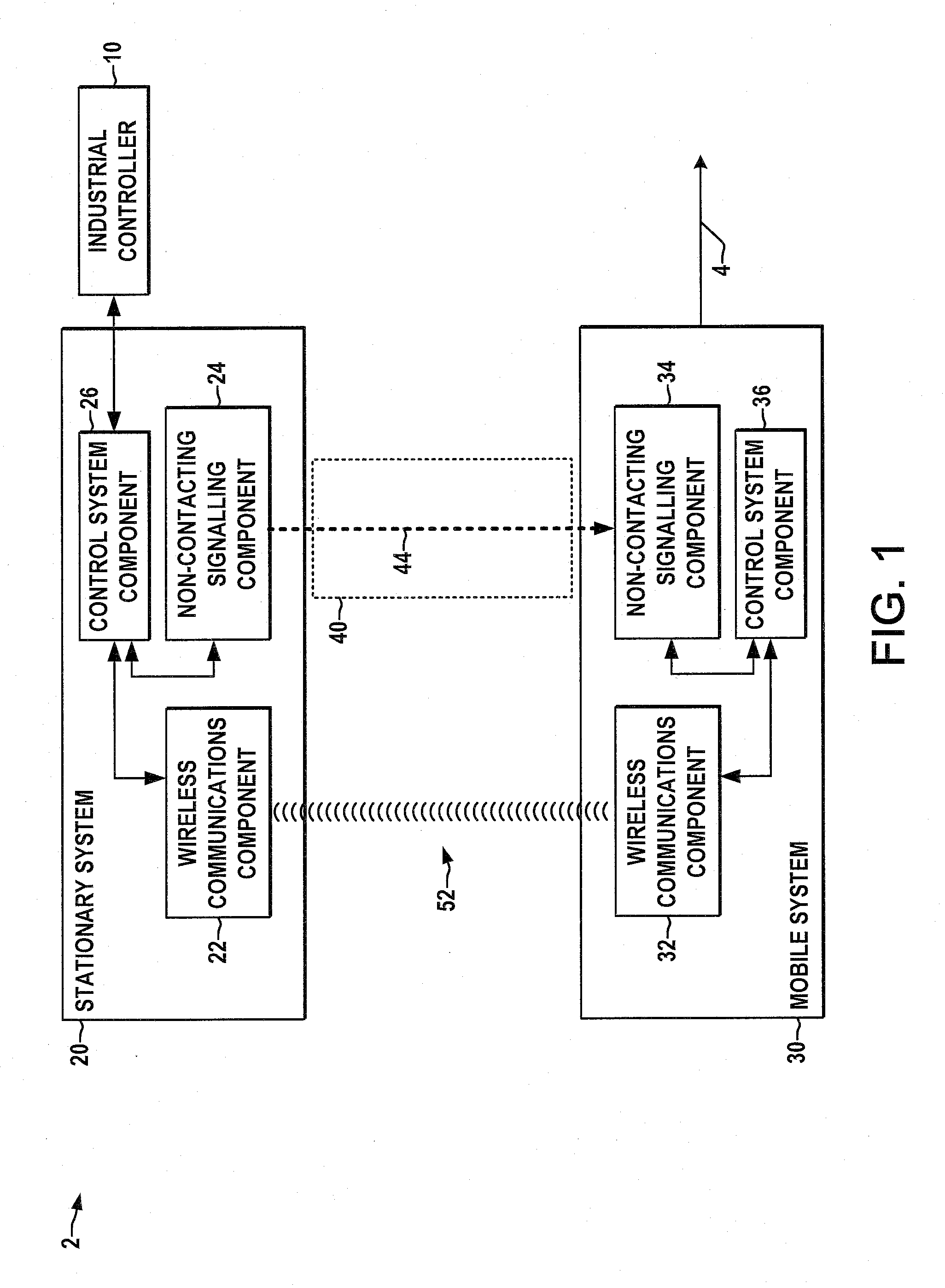
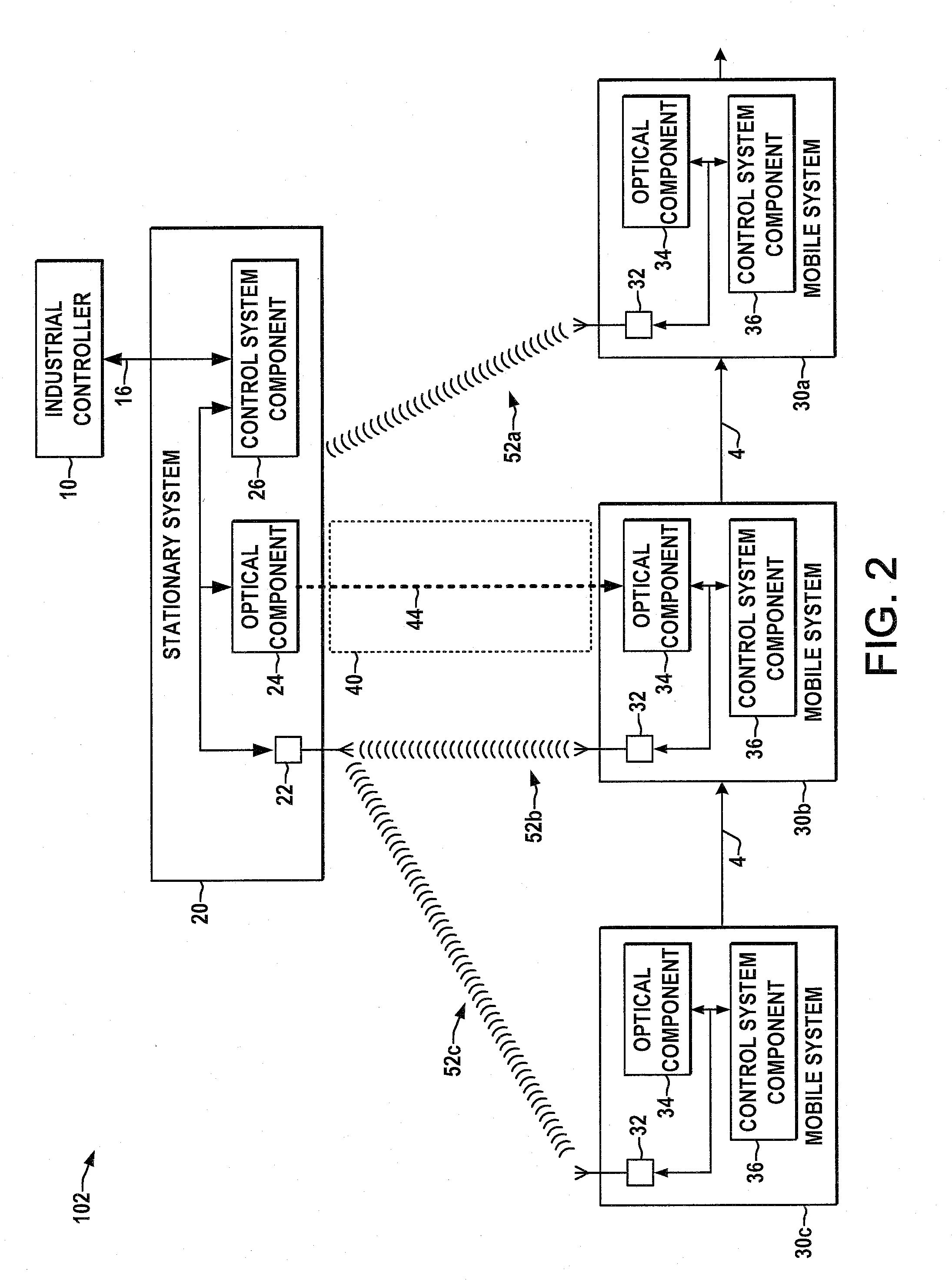
[0021]Referring now to the figures, several embodiments or implementations of the present invention are hereinafter described in conjunction with the drawings, wherein like reference numerals are used to refer to like elements throughout, and wherein the various features are not necessarily drawn to scale. The invention provides methods and systems for control of movable systems in an automated process with a stationary system having a first control system component and a movable system having a second control system component, in which non-contacting signaling between the stationary and movable systems is used to ascertain whether the movable system is proximate the stationary system, and wireless communications is used to transfer control data between the systems while the non-contacting signal link is maintained. In the following examples, different forms of stationary and movable systems are illustrated and described, including stationary equipment associated with a manufacturin...


PUM


Abstract

Control systems and methods are disclosed for controlling operation of movable systems in an automated process with a stationary system having a first control system component and at least one movable system having a second control system component, in which optical or other non-contacting signaling between the stationary and movable systems is used to ascertain whether a movable system is proximate the stationary system, and wireless communications is used to transfer control data between the systems while the non-contacting signal link is maintained.

Description

REFERENCE TO RELATED APPLICATION[0001]This application claims priority to and the benefit of U.S. Provisional Patent Application Ser. No. 60 / 783,530, filed Mar. 17, 2006, entitled SIGHT-LINE OPTICAL COUPLED WIRELESS TECHNOLOGY, the entirety of which is hereby incorporated by reference.FIELD OF THE INVENTION[0002]The present invention relates generally to control systems and more particularly to systems and methods for contact free control of moving systems.BACKGROUND OF THE INVENTION[0003]Control systems or industrial controllers are used for controlling industrial processes such as machines, manufacturing equipment, and other factory automation apparatus. Industrial controllers receive various analog and / or digital process variables or other inputs representative of the status of a controlled process and generate outputs according to a control program or routine to control the process to one or more desired setpoints or other system performance criteria. Industrial control systems ...

Claims


Application Information

Patent Timeline
Patent Type & Authority Applications(United States)
IPC IPC(8): G08C19/00
CPCG05B19/4185G05B2219/33198G05B2219/33192G05B2219/31133Y02P90/02
Inventor PENICK, JERRY L.SICHNER, GREGG M.
Owner ROCKWELL AUTOMATION TECH
Why Eureka
Try Eureka