
Server apparatus of computer system

Inactive Publication Date: 2007-10-04
CASIO COMPUTER CO LTD
View PDF53 Cites 37 Cited by
  • Summary
  • Abstract
  • Description
  • Claims
  • Application Information

AI Technical Summary

Benefits of technology

[0014]The present invention is directed to provide a server apparatus of a computer system which can generate and transfer easy-to-view display screen data even when the size of a display screen of a client apparatus is much less than, for example, a VGA size.
[0015]A server apparatus of the present invention is a server apparatus of a computer system which transmits display data generated in the server apparatus to a client apparatus and which displays the display data on a display screen of the client apparatus, the server apparatus comprising: drawing area setting means for setting an area larger than a display area of the client apparatus as a drawing area of the display data on the basis of display area information from the client apparatus; real display control means for extracting, out of the display data drawn in the drawing area set by the drawing area setting means, display data of an area corresponding to the display area of the client apparatus, and transferring the extracted display data to the client apparatus, when a display command received from the client apparatus is a real display command; and full display control means for reducing the display data drawn in the drawing area set by the drawing area setting means in accordance with the display area of the client apparatus, and transferring the reduced display data to the client apparatus, when a display command received from the client apparatus is a full display command.
[0016]According to such a server apparatus of the present invention, a display area of, for example, a VGA size larger than the display area of the client apparatus is set as the drawing area for the display data on the basis of the information on the display area of the client apparatus. When a display command received from the client apparatus is a real display command, display data of an area corresponding to the display area of the client apparatus is extracted out of the display data drawn in the set drawing area, and transferred to and displayed on the client apparatus. On the other hand, when a display command received from the client apparatus is a full display command, the display data drawn in the set drawing area is reduced in accordance with the display area of the client apparatus, and transferred to and displayed on the client apparatus. Thus, even when the connected client apparatus is, for example, a PDA, and the size of its display screen is significantly small, an original data display area can be displayed as widely as possible and in an easy-to-view manner without the occupation of a large space within the display screen by the area for user operation.
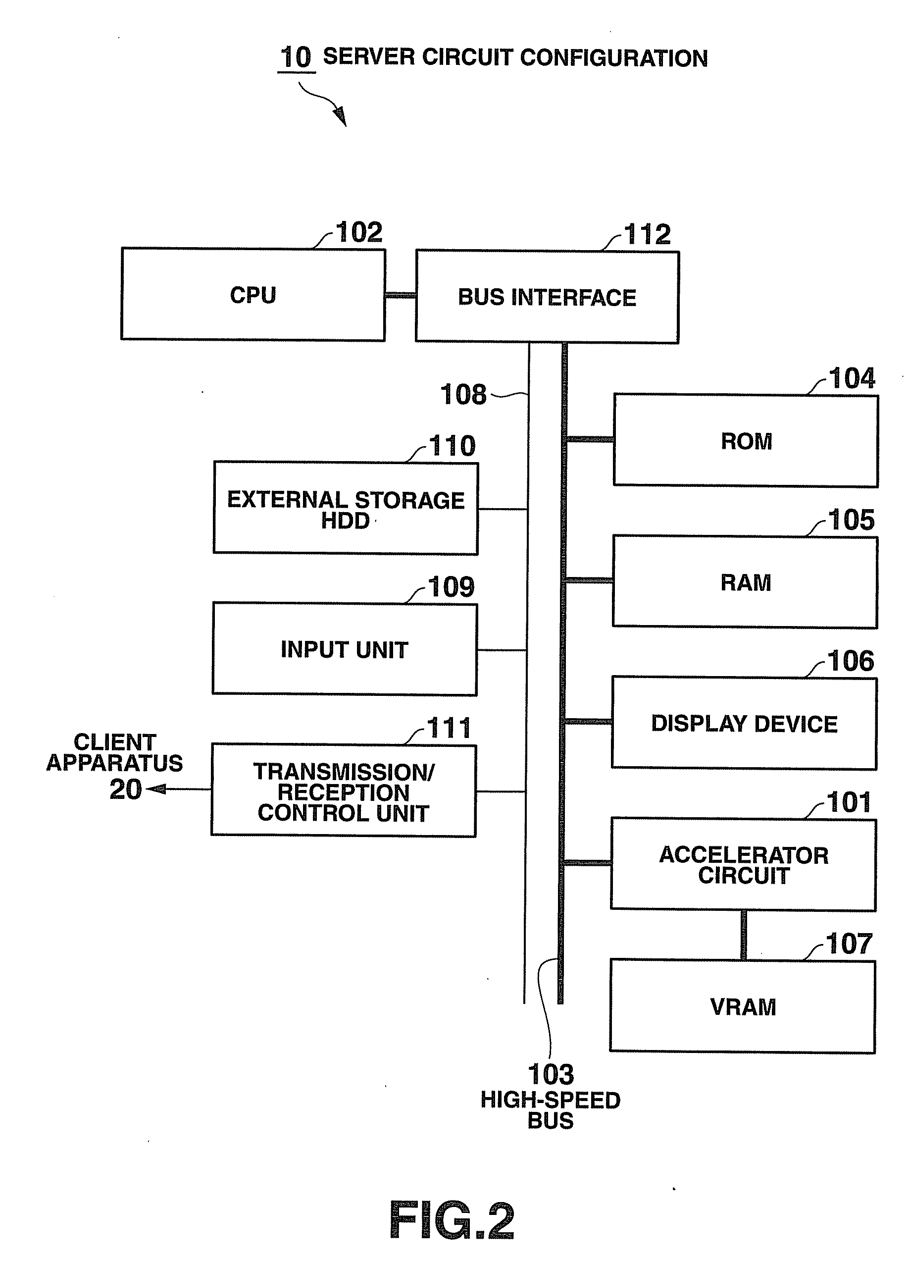
[0018]According to such a server apparatus of the present invention, the magnification changing circuit, the area dividing circuit and the judging circuit are formed by hardware at the time of generating the display data which is transmitted to the client apparatuses so that it is possible to generate the display data which is transmitted to the client apparatus at high velocity while reducing the load on control means. Moreover, because the load on the control means is reduced, the number of client apparatuses to be connected can be increased accordingly.

Problems solved by technology

In such a conventional client-server system, the created files are managed in each of the PC terminals itself, so that the saved files might be read to result in the leakage of important information or secret information in case where the PC terminal is lost or illegally taken out and passed to a third party.
Moreover, when each of the PC terminals individually starts and executes the application, the tasks of updating, modifying and adding to the application have to be carried out for each of the PC terminals, leading to troublesome management and increased costs.
Therefore, a large space within the display screen is occupied by the area for user operation, so that an original data display area (cell area) is significantly reduced and becomes extremely difficult to view, resulting in a problem of a decrease in the operability for inputting data.

Method used


Image

  • Server apparatus of computer system
  • Server apparatus of computer system
  • Server apparatus of computer system

Examples


first embodiment

[0051]the present invention will hereinafter be described with reference to the drawings.

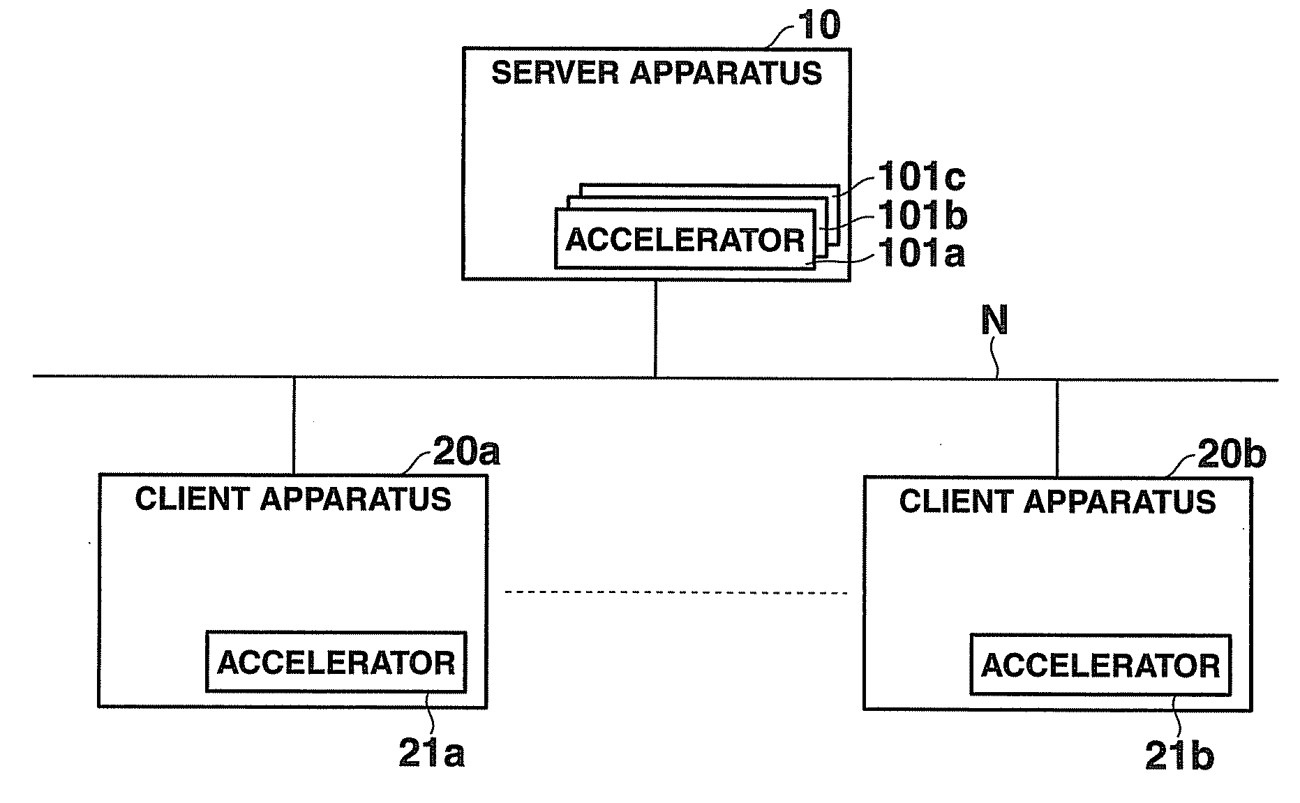
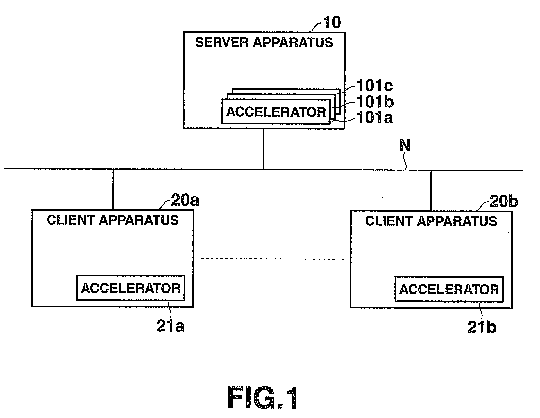
[0052]FIG. 1 is a block diagram showing the configuration of a thin client system comprising a server apparatus 10 according to the embodiment of the present invention, and its client apparatuses 20a, 20b, . . . .

[0053]This thin client system comprises the server apparatus 10 and the plurality of client apparatuses 20a, 20b, . . . that are connected on a network N including a local area network (LAN) or a wide area network (WAN).

[0054]The server apparatus 10 has a plurality of application programs such as a document creation processing program, a table creation processing program, a mail processing program, an Internet connection processing program and a Web display program, and the server apparatus 10 starts the program and executes its processing in response to an operation input signal from the client apparatus 20a, 20b, . . . connected to the server apparatus 10.

[0055]In this server apparat...

second embodiment

[0169]Next, the present invention will be described in detail. A block diagram showing a schematic configuration of a computer system comprising the server apparatus 10 according to the embodiment of the present intention and a plurality of client apparatuses 20a, 20b, . . . (hereinafter indicated representatively as 20) is similar to FIG. 1, and will not be described.

[0170]FIGS. 18A, 18B and 18C are diagrams showing how the drawing data generated in the server apparatus 10 of the present computer system is transferred to and displayed on the client apparatus 20; wherein 18A is a diagram showing how the drawing data changes in the server apparatus 10, 18B is a diagram showing the transfer display data during the change of the drawing data, and 18C is a diagram showing how the transferred drawing data is displayed / output in the client apparatus 20.

[0171]In the server apparatus 10, when drawing data (before change) G already generated in accordance with the working application program...


PUM


Abstract

When a display command received from a client apparatus is a real display command, a real display control unit extracts, out of the display data drawn in the drawing area, display data of an area corresponding to the display area of the client apparatus, and transferring the extracted display data to the client apparatus. When a display command received from the client apparatus is a real display command, a full display control unit reduces the display data drawn in the drawing area in accordance with the display area of the client apparatus, and transferring the reduced display data to the client apparatus. Even when the size of a display screen is small, the display data in the display area corresponding to a request from the client apparatus is transferred so that the display data can be displayed on the client apparatus in an easy-to-view manner.

Description

CROSS-REFERENCE TO RELATED APPLICATIONS[0001]This application is based upon and claims the benefit of priority from prior Japanese Patent Applications No. 2006-091628, filed Mar. 29, 2006; and No. 2006-095744, filed Mar. 30, 2006, the entire contents of both of which are incorporated herein by reference.BACKGROUND OF THE INVENTION[0002]1. Field of the Invention[0003]The present invention relates to a server apparatus of a computer system (thin client), wherein all applications which are input / output and displayed by a client personal computer (PC) are operated on a server, in a client-server system connected via a network such as a local area network (LAN).[0004]2. Description of the Related Art[0005]Traditionally, each PC terminal connected to a network such as an in-house LAN individually starts and executes an application such as a document creation or table creation application, and various files created accordingly are saved in a storage device of each of the PC terminals, or s...

Claims


Application Information

Patent Timeline
IPC IPC(8): G06F3/048G06F17/00G06F15/00G06T15/30
CPCG06T15/30G06T11/00
Inventor OHTSUKA, TOSHIHIKOHIROTANI, TAKAYUKI
Owner CASIO COMPUTER CO LTD
Learn More