
Pneumatic tire

a technology of pneumatic tires and sidewalls, applied in the field of pneumatic tires, can solve the problems of uneven stiffness in the sidewall, poor linearity of tires, etc., and achieve the effects of high stiffness, high elasticity, and lateral stiffness

Inactive Publication Date: 2007-10-11
SUMITOMO RUBBER IND LTD
View PDF5 Cites 5 Cited by
  • Summary
  • Abstract
  • Description
  • Claims
  • Application Information

AI Technical Summary

Benefits of technology

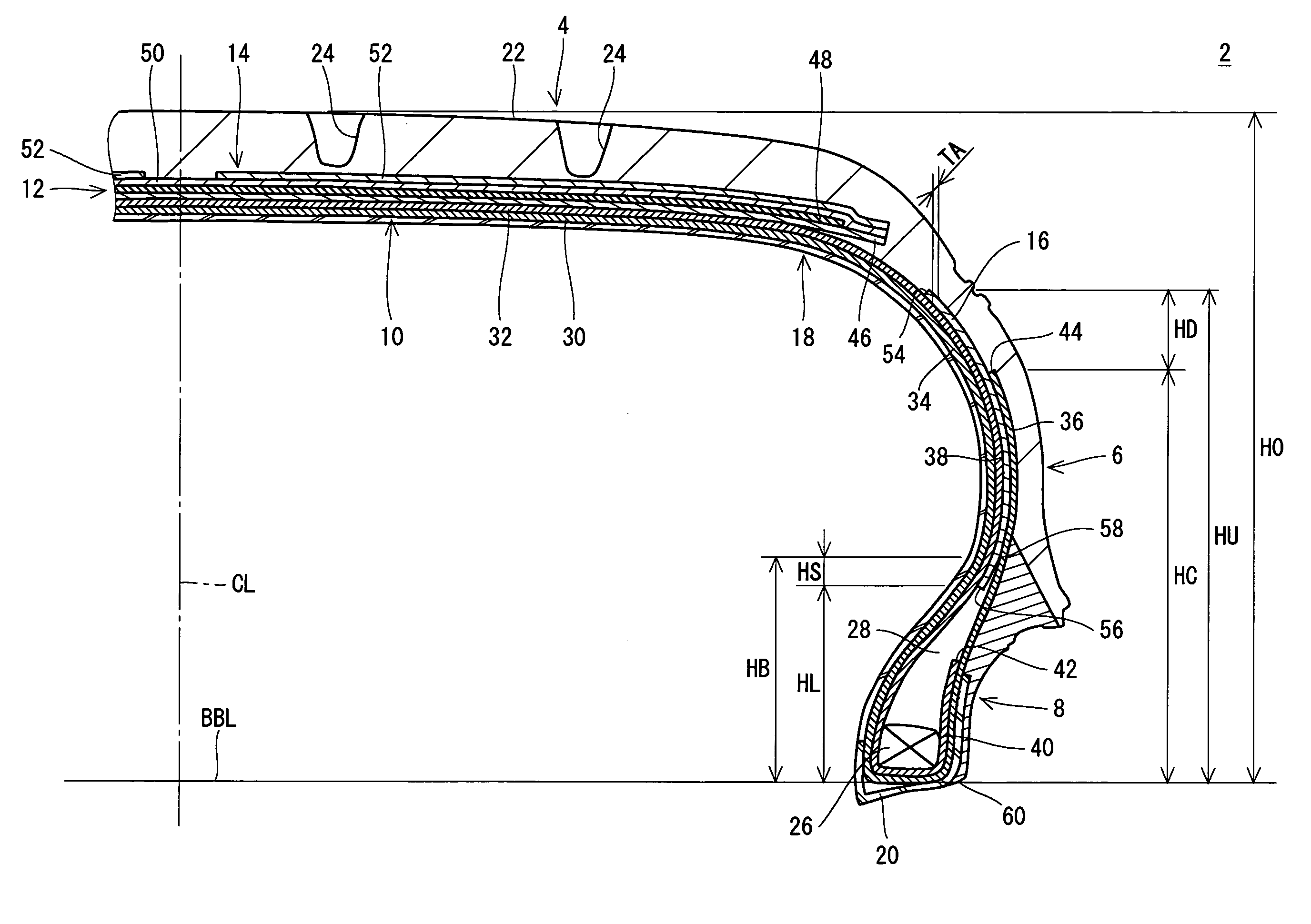
[0013]In the tire, there is used the carcass cord formed by the polyethylene naphthalate fiber having a higher elasticity than that of a polyethylene terephthalate fiber. Therefore, the tire has a high stiffness. In the tire, the reinforcing layer having the thickness and the hardness regulated properly can contribute to a lateral stiffness while suppressing a rise in a vertical stiffness. The tire is excellent in a handling stability. In the tire, it is not necessary to include an apex having a great height in a radial direction in order to enhance the handling stability. A tire having a rise in a vertical stiffness suppressed is excellent in a ride comfort. The reinforcing layer generates a uniform stiffness in the sidewall. Therefore, the tire is also excellent in a linearity.

Problems solved by technology

A stiffness in a sidewall is not uniform.
For this reason, the tire has a poor linearity.

Method used


Image

  • Pneumatic tire
  • Pneumatic tire

Examples


example 1

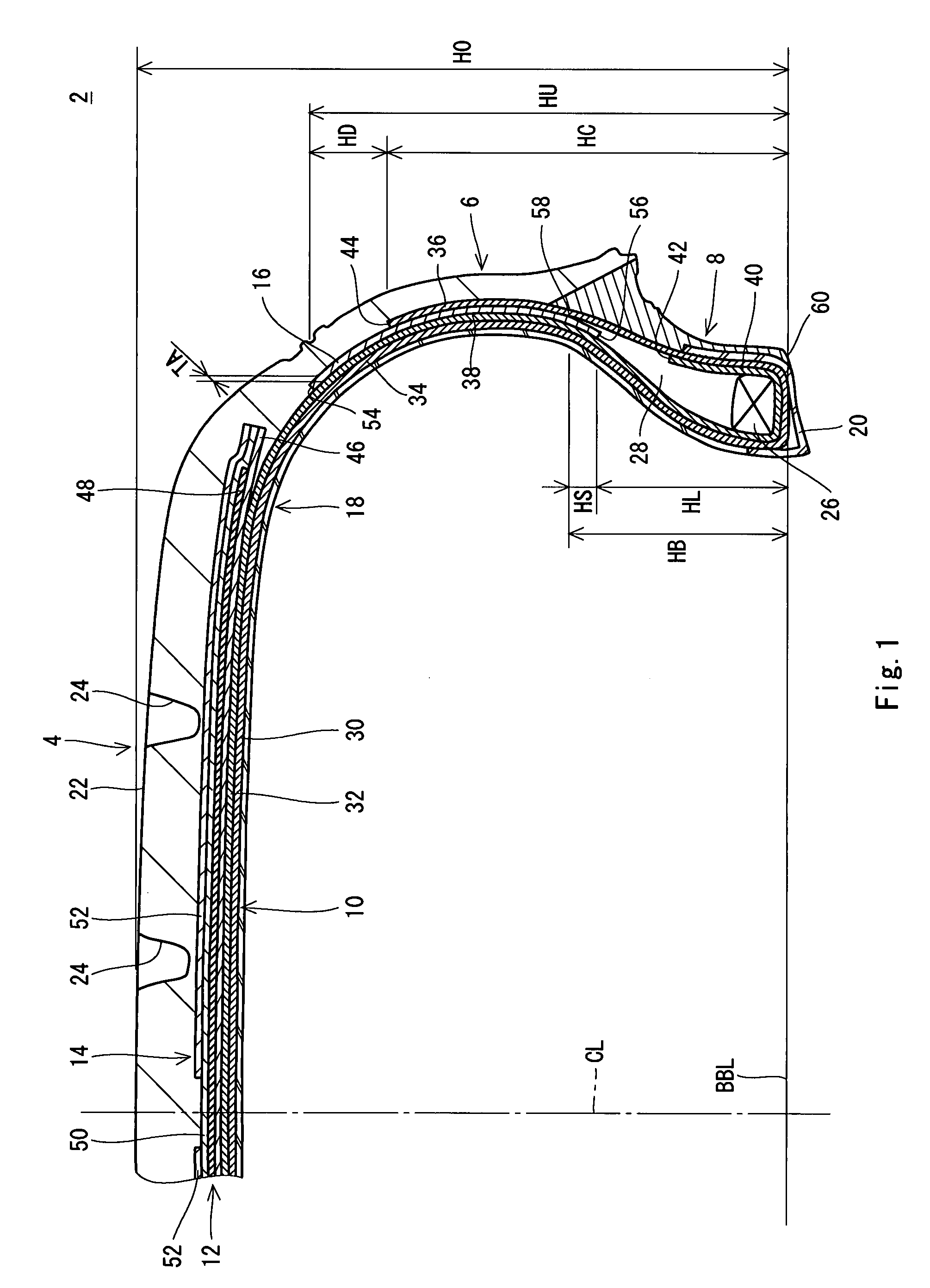
[0046]There was obtained a pneumatic tire for a car according to an example 1 which has the basic structure shown in FIG. 1, uses, for a carcass cord, a cord B having a specification shown in the following Table 1 and has a specification shown in the following Table 2. The tire has a size of “245 / 45R18”. A reinforcing layer of the tire has a thickness TA of 1.0 mm. A hardness of the reinforcing layer which was measured on a condition of a temperature of 25° C. is 90. A ratio (HU / H0×100) of a height HU in a radial direction from a bead base line BBL to an upper end of the reinforcing layer to a tire sectional height H0 is 75%. A ratio (HC / H0×100) of a height HC in the radial direction from the bead base line BBL to a turned-up end of a carcass to the tire sectional height H0 is 60%. A ratio (HB / H0×100) of a height HB in the radial direction from the bead base line BBL to an upper end of an apex to the tire sectional height H0 is 30%. A ratio (HL / H0×100) of a height HL in the radial d...

examples 4 , 13 and 14

Examples 4, 13 and 14

[0047]A tire was obtained in the same manner as in the example 1 except that the thickness TA of the reinforcing layer was set as shown in the following Tables 2 and 3.

examples 3 , 6 and 15

Examples 3, 6 and 15

[0048]A tire was obtained in the same manner as in the example 1 except that the hardness of the reinforcing layer was set as shown in the following Tables 2 and 3.


PUM


Abstract

A tire (2) according to the present invention includes a bead (8) having an apex (28), a carcass (10) and a reinforcing layer (16). The carcass (10) includes a carcass ply having a carcass cord constituted by a polyethylene naphthalate fiber. The carcass ply is constituted by a body extended from an equator plane toward the bead (8) and a turned-up portion extended outward in a radial direction. The reinforcing layer (16) is interposed between the body and the turned-up portion. A ratio of a height in the radial direction from a bead base line to an upper end (54) of the reinforcing layer (16) to a tire sectional height is equal to or higher than 45%. A thickness of the reinforcing layer (16) is equal to or greater than 0.3 mm and is equal to or smaller than 2.5 mm. A hardness of the reinforcing layer (16) is equal to or greater than 70 and is equal to or smaller than 95.

Description

[0001]This application claims priority on Patent Application No. 2006-107622 filed in JAPAN on Apr. 10, 2006, the entire contents of which are hereby incorporated by reference.BACKGROUND OF THE INVENTION[0002]1. Field of the Invention[0003]The present invention relates to a pneumatic tire.[0004]2. Description of the Related Art[0005]In a radial tire for a car, organic fibers such as a nylon fiber, a rayon fiber and a polyester fiber are used for a material of a carcass cord. In respect of an enhancement in a handling stability, the polyester fiber having a high elasticity is mainly used for the material of the carcass cord.[0006]A pneumatic tire which is excellent in a handling stability and a ride comfort has been disclosed in Japanese Laid-Open Patent Publication No. 2005-178520. Referring to the tire, a carcass cord formed by a polyethylene naphthalate fiber as a material thereof is used and a twist coefficient and an elongation of the carcass cord are optimized.[0007]A bead of t...

Claims


Application Information

Patent Timeline
Patent Type & Authority Applications(United States)
IPC IPC(8): B60C15/06B60C9/02
CPCB60C9/14B60C2009/2219Y10T152/10837Y10T152/10864B60C2015/0617
Inventor TANAKA, SUSUMU
Owner SUMITOMO RUBBER IND LTD
Learn More