Apparatus and method for ultra narrow band communications

a technology of ultra-narrow band communication and apparatus, applied in the field of digital communication protocols and circuits, can solve the problems of limitation imposed by previously available filtering methods, and achieve the effect of reducing noise bandwidth and greatly reducing noise power in the received phase shift keyed digital data

Inactive Publication Date: 2007-10-11
WALKER HAROLD R
View PDF5 Cites 30 Cited by
  • Summary
  • Abstract
  • Description
  • Claims
  • Application Information

AI Technical Summary

Benefits of technology

[0010] The output of a phase detector utilizing the present method is found not to be linearly related to the level of any sidebands, which have been greatly reduced or removed in the present invention. The method tolerates interference at levels far in excess of what would have been the J1 sideband levels, indicating that the sidebands are not being used to carry the modulation information, which is not the case with the commonly used phase or frequency modulation methods. Signal-to-noise ratios for a given error rate, are comparable to, or better than, that of the other commonly used methods requiring a full Nyquist bandwidth, since the receiver filter noise bandwidth is greatly reduced.
[0012] The method further comprises receiving such modulated data. It comprises the steps of reducing noise bandwidth with an ultra narrow bandpass filter, detecting abrupt phase changes, and decoding the detected abrupt phase changes into digital ones and zeros along with a corresponding data clock. The invention comprises the step of using a filter having a noise bandpass narrower than the Nyquist bandwidth of the phase shifted keyed digital data, so that information encoded in the phase changes in the signal is to be found in the carrier alone. The filter has a noise bandpass narrower than the Nyquist bandwidth of the phase shifted keyed digital data so that the noise power in the received phase shift keyed digital data is greatly reduced compared to that of conventionally generated phase modulated signals. The method further comprises the step of providing pulses of a polarity indicating a digital one or zero and synchronizing a recovered data clock with the received abrupt phase change pulses.

Problems solved by technology

This is a limitation imposed by the previously available filtering methods and the method used to generate the phase modulation.

Method used


Image

  • Apparatus and method for ultra narrow band communications
  • Apparatus and method for ultra narrow band communications
  • Apparatus and method for ultra narrow band communications

Examples


Embodiment Construction

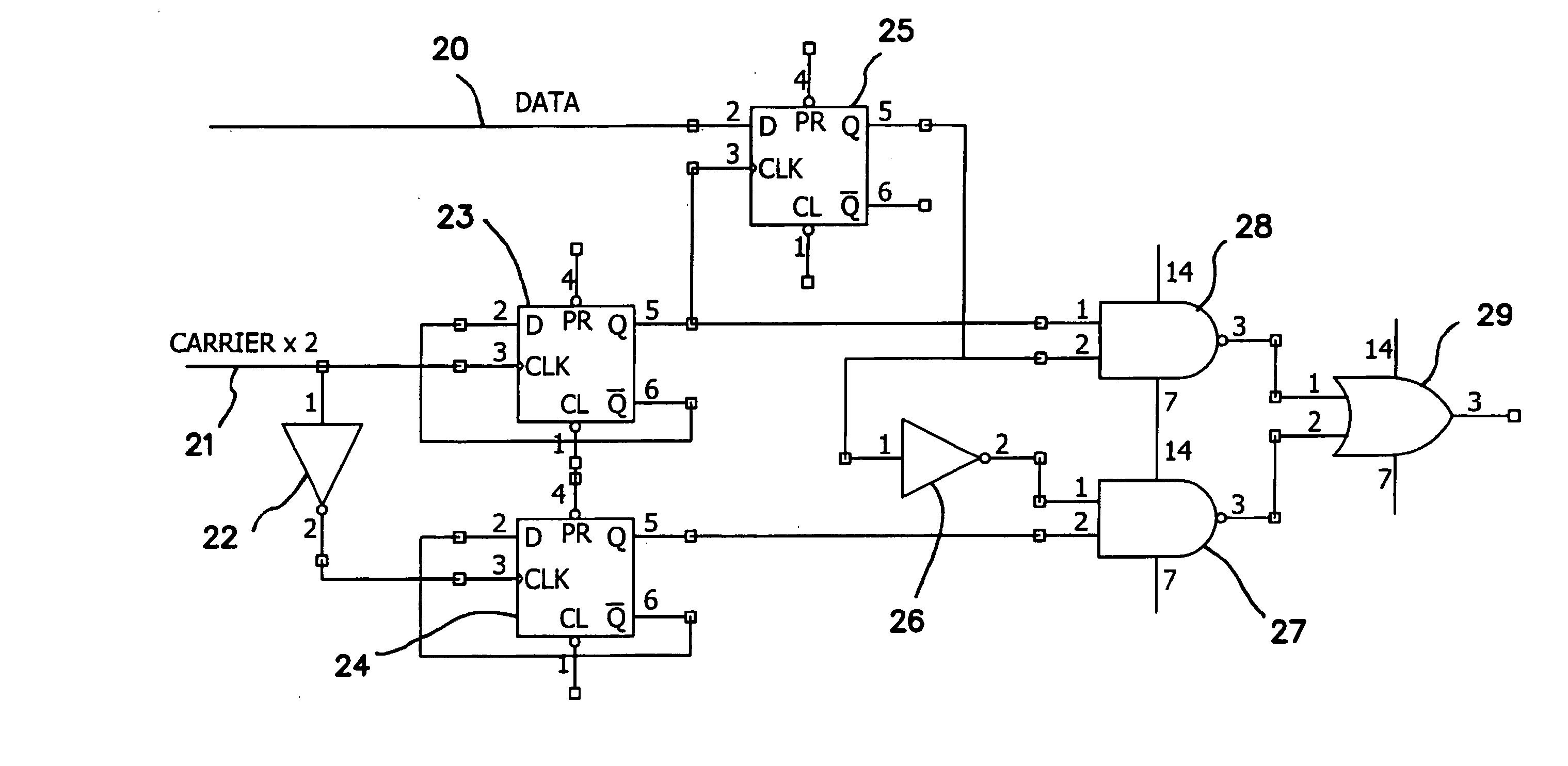
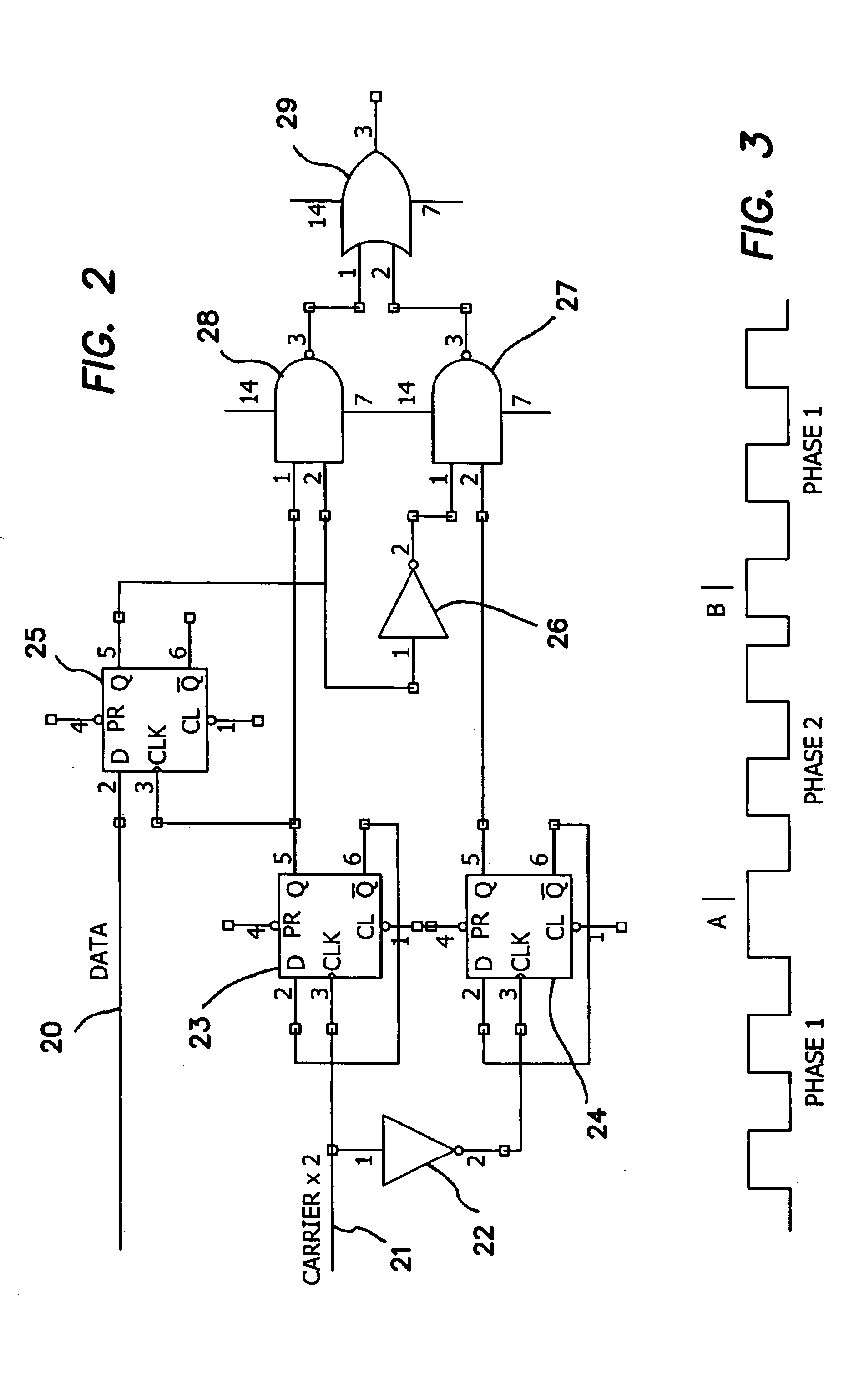
[0038] Embodiments of the present invention combine abrupt phase shift keying with the Walker Shunt filters according to the invention to remove the Fourier sidebands. Unlike commonly used methods, which utilize CPFSK, a method in accordance with an embodiment of the invention utilizes abrupt change phase shift keying. The transmitted signal is the carrier alone, which has no theoretical or visible frequency shift. The method makes it possible to use non return to zero (NRZ) data as the input, as is done with bi-phase shift key modulation (BPSK), but using 90 degrees or less of total abrupt phase change instead of the 180 degrees used with BPSK. The Walker shunt filters have essentially no rise time and zero group delay, so that they respond to the abrupt phase change edges as well as to the overall phase change. Conventional filters introduce a time delay and cannot respond to the necessary abrupt phase change. This unusual characteristic of these shunt filters, along with the uniq...


PUM


Abstract

A method and apparatus for transmitting information combining abrupt phase change modulation with an ultra narrow band filter to remove unnecessary Fourier sidebands, resulting in a single frequency being transmitted to carry data. The method examines and detects the changes in the carrier phase only, after filtering to remove or reduce all sidebands, to obtain a usable signal. Only a single frequency with phase changes is transmitted. An ultra narrow band filter, having a rapid rise time and near zero group delay, passes the near instantaneous modulation changes of phase in the carrier.

Description

CROSS REFERENCE TO RELATED APPLICATIONS [0001] The present application is a continuation-in-part of U.S. patent application Ser. No. 10 / 689,911, filed on Oct. 21, 2003, which claims benefit of U.S. Provisional Patent Application Ser. No. 60 / 420,239, filed on Oct. 22, 2002, both incorporated herein by reference in their entirety.BACKGROUND OF THE INVENTION [0002] 1. Field of the Invention [0003] The invention relates to the field of digital communication protocols and circuits, and in particular to phase modulation communication protocols and circuits using only the carrier frequency, without sidebands, for information transmittal or reception. [0004] 2. Description of the Prior Art [0005] Ultra narrow band methods must separate the carrier from the sidebands, transmitting only one or the other. The object is to obtain a single modulation-bearing frequency, or very narrow band of frequencies, that will occupy the least possible transmission bandwidth. U.S. Pat. Nos. 4,742,532, 5,185,...

Claims


Application Information

Patent Timeline
Patent Type & Authority Applications(United States)
IPC IPC(8): H03H7/38H04L27/20
CPCH04L27/2035
Inventor WALKER, HAROLD R.
Owner WALKER HAROLD R
Why Eureka
Try Eureka