Burner system with staged fuel injection

a fuel injection and burner technology, applied in the direction of machines/engines, combustion types, lighting and heating apparatus, etc., can solve the problem of no longer ensuring the correct operation of the combustion installation, and achieve the effect of avoiding the extinction of flames and minimising pollutant emissions

Inactive Publication Date: 2007-10-11
ANSALDO ENERGIA IP UK LTD
View PDF9 Cites 2 Cited by
  • Summary
  • Abstract
  • Description
  • Claims
  • Application Information

AI Technical Summary

Benefits of technology

[0004] The present invention addresses the problem of, on the one hand operating a burner system as close as possible to the lean extinction limit and therefore with minimum possible pollutant emissions, and on the other hand of avoiding extinction of the flame in the burner system.

Problems solved by technology

Operating a combustion installation close to its lean extinction limit, although on the one hand leading to low pollutant emission levels, on the other hand also conceals the risk of the flame being extinguished as a result of pulsating pressures, with the result that correct operation of the combustion installation is no longer ensured.

Method used


Image

  • Burner system with staged fuel injection
  • Burner system with staged fuel injection

Examples


Embodiment Construction

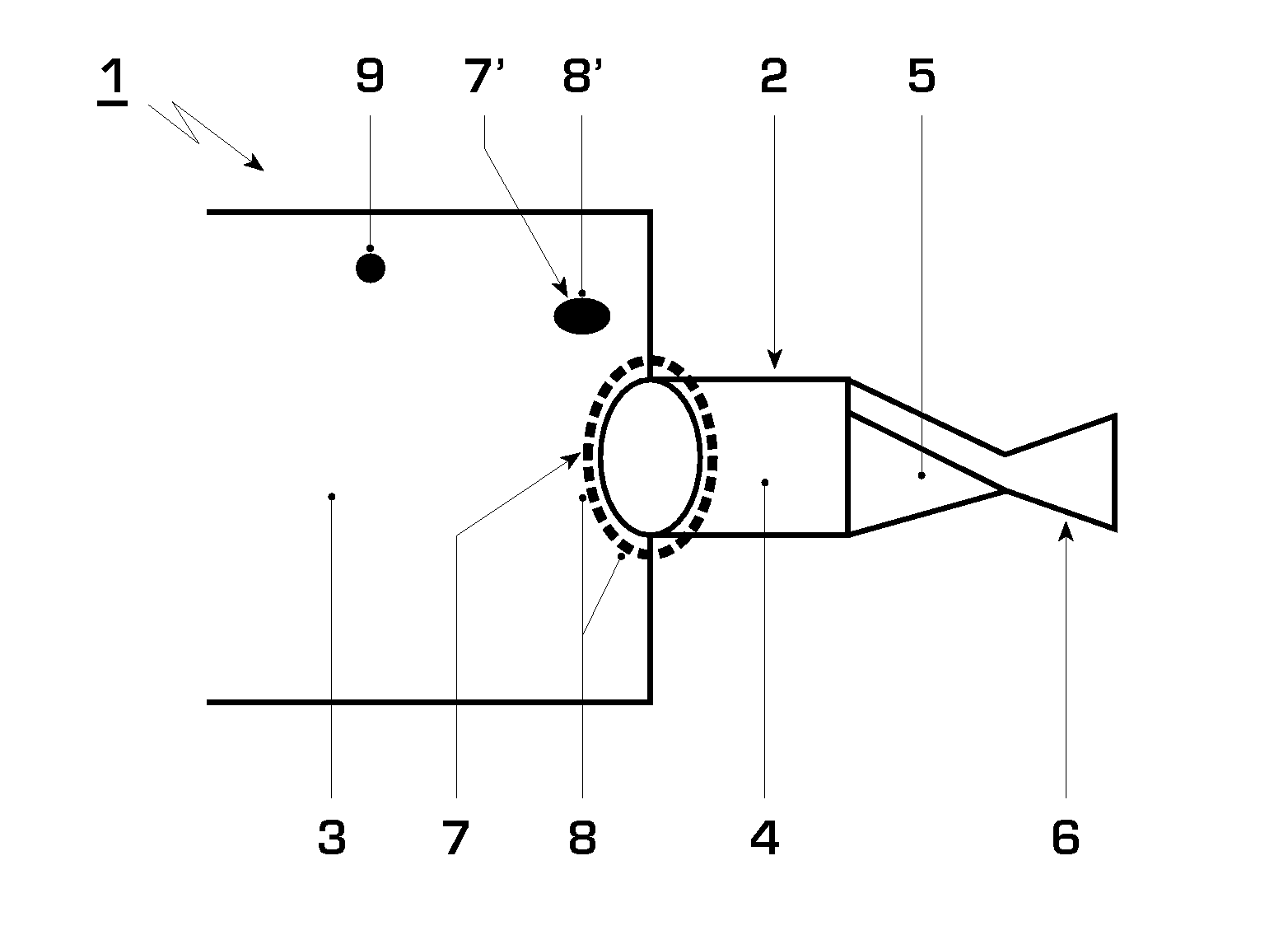
[0014] In accordance with FIG. 1, a burner system 1 according to the invention with staged fuel injection has at least one burner 2. A combustion chamber 3, a mixing zone 4 and an inflow region 5 of the burner 2 are arranged from left to right in FIG. 1. The inflow region 5 may, for example, be designed as a swirl generator and may impart a swirling movement to the fuel / air mixture flowing into the mixing zone 4. By way of example, a gas turbine (not shown) may be located downstream of the combustion chamber 3.

[0015] A first fuel introduction device 6, which passes fuel into the inflow region 5, is arranged in the inflow region 5 or downstream of the mixing zone 4. According to the invention, a second fuel introduction device 7, which is designed for the direct injection or introduction of fuel into the combustion chamber 3, is arranged downstream of the mixing zone 4. FIG. 1 illustrates two different types of the second fuel introduction device 7 or 7′, the fuel introduction devic...


PUM


Abstract

A burner system with staged fuel injection includes at least one burner with a mixing zone. A combustion chamber is disposed downstream of the mixing zone and a first fuel introduction device is provided upstream of the mixing zone. Furthermore, a second fuel introduction device for the direct injection of fuel into the combustion chamber, is disposed downstream of the mixing zone. In addition, at least one sensor for determining combustion parameters is connected to a control device. The control device is designed to control the second fuel introduction device as a function of the parameters determined by the sensors.

Description

[0001] Priority is claimed to German Patent Application No. DE 10 2006 015 529.7, filed on Mar. 31, 2006, the entire disclosure of which is incorporated by reference herein. [0002] The present invention relates to a burner system with staged fuel injection and to a method for controlling a burner system of this type. BACKGROUND [0003] The increasingly stringent regulations governing pollutant emission limits are compelling power plant operators to operate the burners of the power plants as far as possible in lean-burn mode, i.e. with a considerable excess of oxidizing agent, generally air. The lean-burn operation makes it possible in particular to reduce the formation of particularly harmful NOx emissions and at the same time to move the combustion reaction close to its lean extinction limit. Operating a combustion installation close to its lean extinction limit, although on the one hand leading to low pollutant emission levels, on the other hand also conceals the risk of the flame ...

Claims


Application Information

Patent Timeline
Patent Type & Authority Applications(United States)
IPC IPC(8): F23Q9/00F23D14/46F23N5/00
CPCF02C7/228F02C9/34F02C9/40F23N5/022F23N2225/04F23N2225/06F23N2225/26F23N2237/02F23R3/346F23R3/36
Inventor GARAY, MAURICIOBERNERO, STEFANOSCHUERMANS, BRUNOZAJADATZ, MARTIN
Owner ANSALDO ENERGIA IP UK LTD
Why Eureka
Try Eureka