

Honeycomb filter defect detecting method and apparatus
a honeycomb filter and filter body technology, applied in the field of honeycomb filter defect detection methods and apparatuses, can solve the problem of easy identification of defective cells/plugs, and achieve the effect of improving signal-to-noise ratio and defect detection
- Summary
- Abstract
- Description
- Claims
- Application Information
AI Technical Summary
Benefits of technology
Problems solved by technology
Method used
Image

Examples
Embodiment Construction
[0018] The invention will now be described in detail with reference to a few preferred embodiments, as illustrated in accompanying drawings. In the following description, numerous specific details are set forth in order to provide a thorough understanding of the invention. However, it will be apparent to one skilled in the art that the invention may be practiced without some or all of these specific details. In other instances, well-known features and / or process steps have not been described in detail in order to not unnecessarily obscure the invention. The features and advantages of the invention may be better understood with reference to the drawings, discussions, and claims that follow.
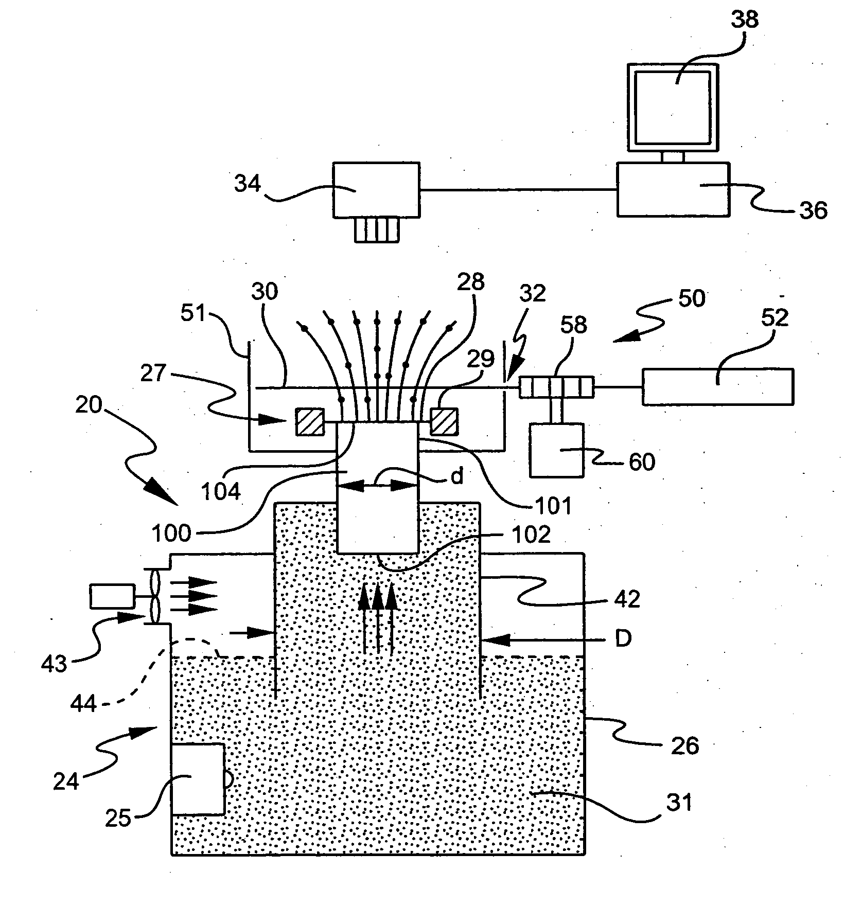
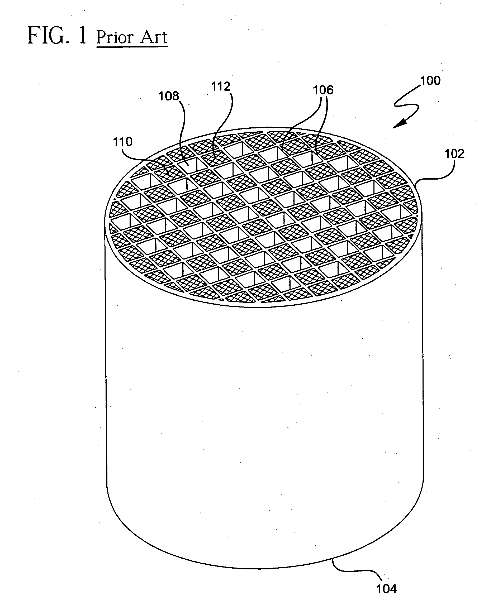
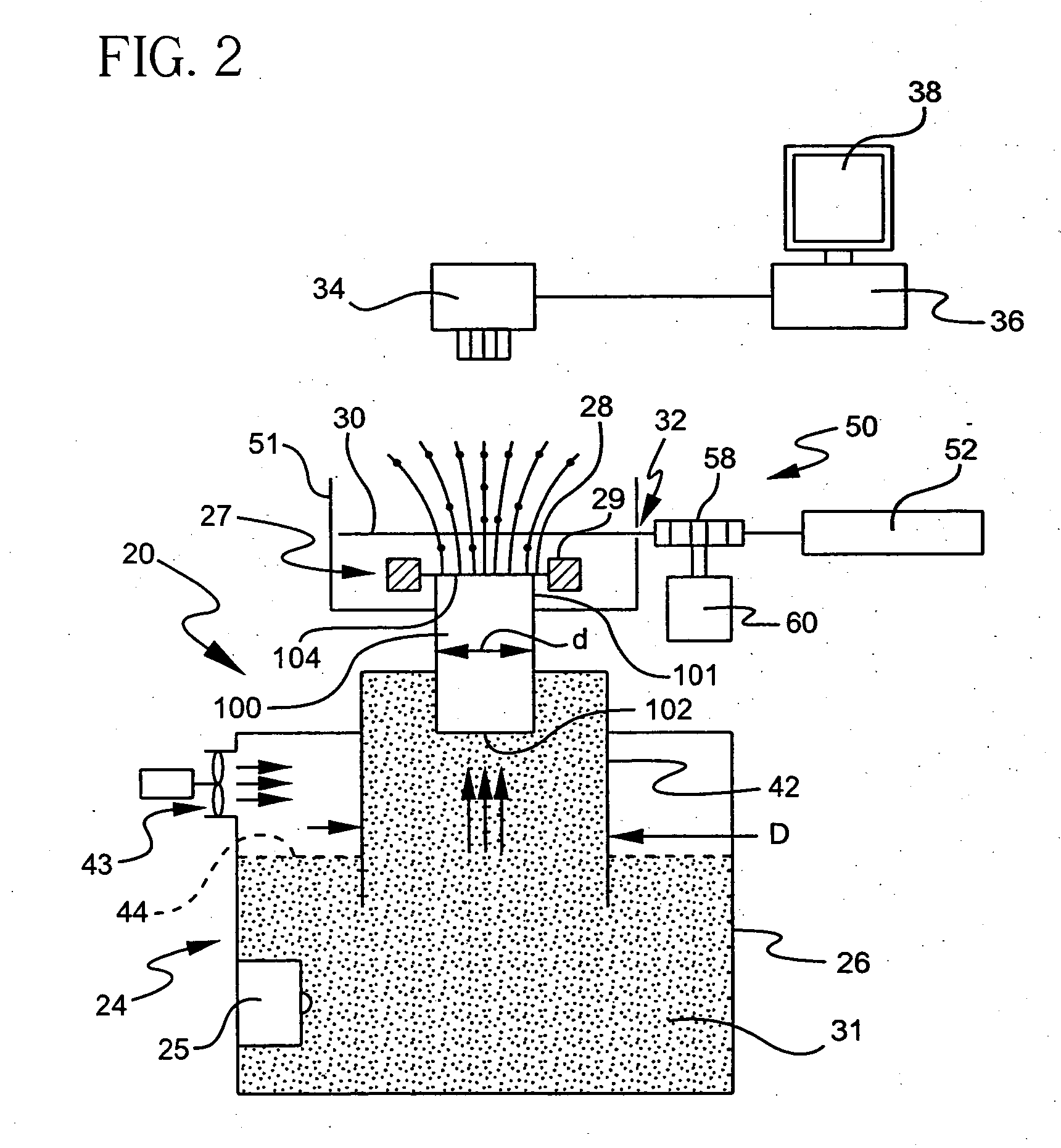
[0019] The apparatus of the invention, as best illustrated in FIG. 2, provides a device 20 for detecting defects in a honeycomb body 100 having cells (channels) that are selectively end-plugged, such as in a wall flow filter or diesel particulate filter. The interior walls and / or plugs of the hone...
PUM
| Property | Measurement | Unit |
|---|---|---|
| pressure | aaaaa | aaaaa |
| diameter | aaaaa | aaaaa |
| operating pressure | aaaaa | aaaaa |
Abstract
Description
Claims
Application Information