
Apparatus for performing storage virtualization

a technology for storage virtualization and apparatus, applied in the field of communication, can solve the problems of slow data function performance, large amount of functionality resident on one piece of hardware and/or software, etc., and achieve the effect of simplifying the writing of partner applications

Active Publication Date: 2007-10-11
AVAGO TECH INT SALES PTE LTD
View PDF13 Cites 328 Cited by
  • Summary
  • Abstract
  • Description
  • Claims
  • Application Information

AI Technical Summary

Benefits of technology

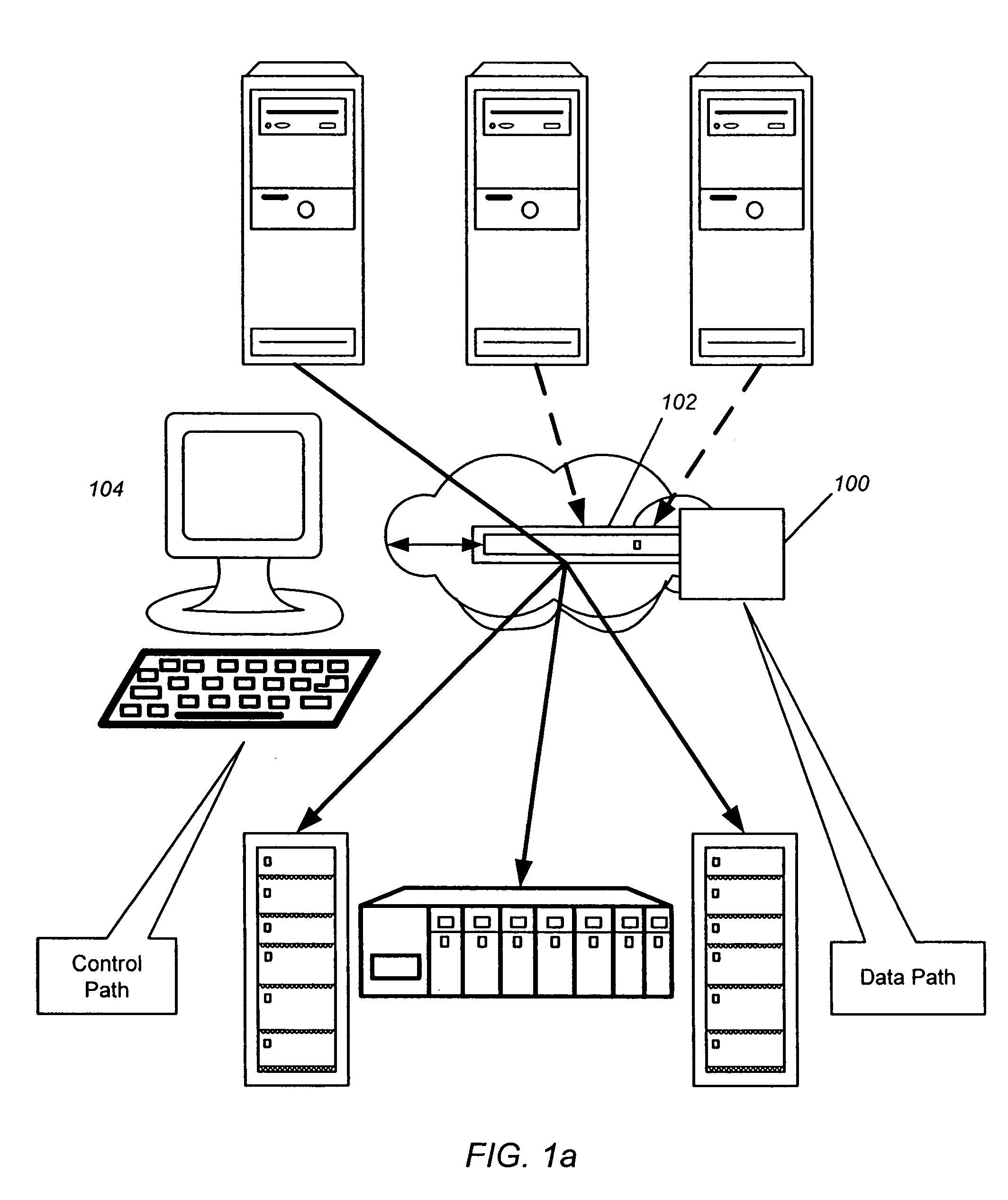
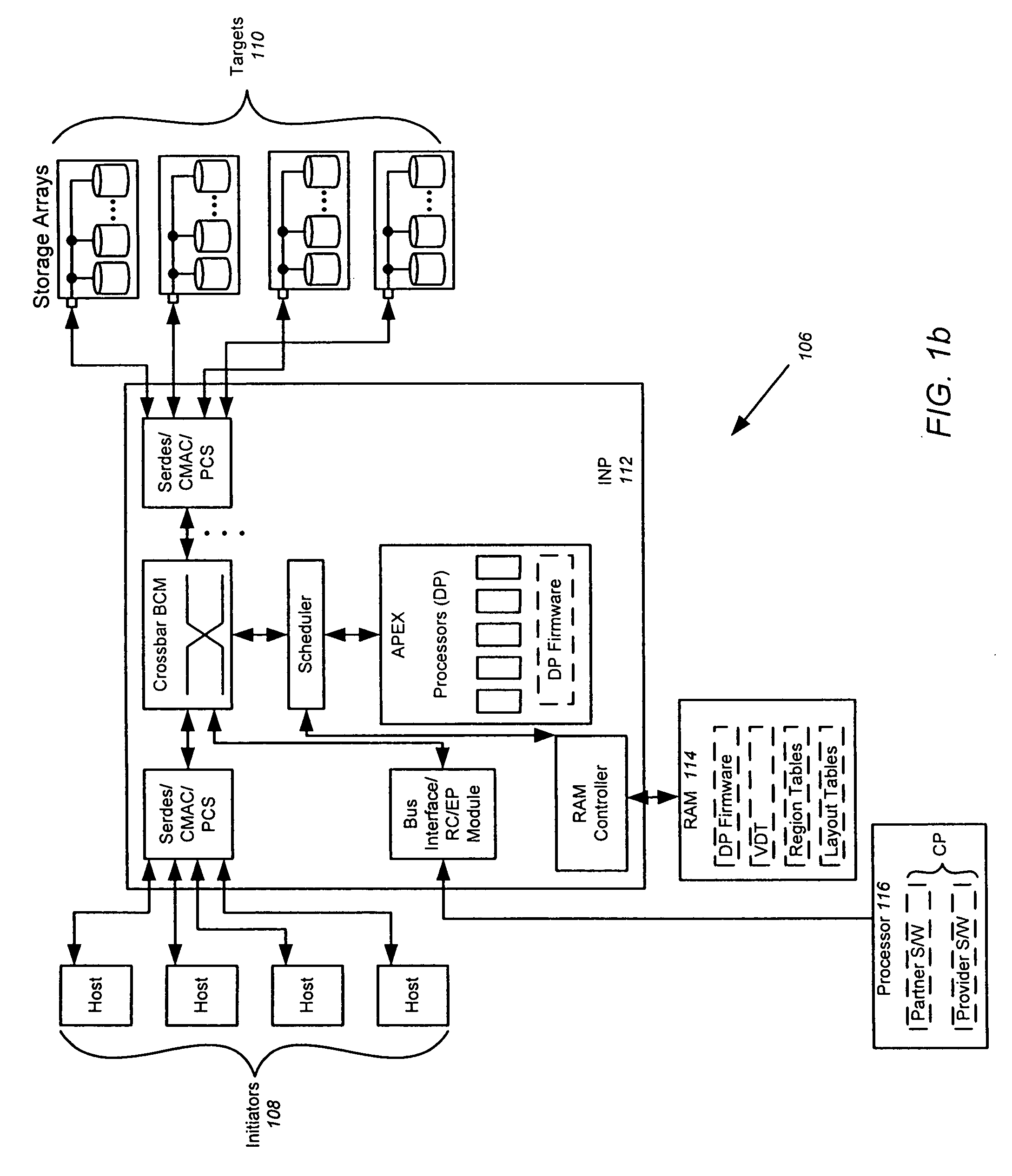
[0006] Embodiments of the invention are directed to the splitting of storage applications and functions into a CP component and a DP component. Reads and writes may be handled primarily in the DP. The CP may be responsible for discovery, configuration, and exception handling. The CP can also be enabled for orchestrating complex data management operations such as snapshots and migration. This bifurcation of functions can lead to increased throughput and flexible and dynamic management capabilities without high overhead.
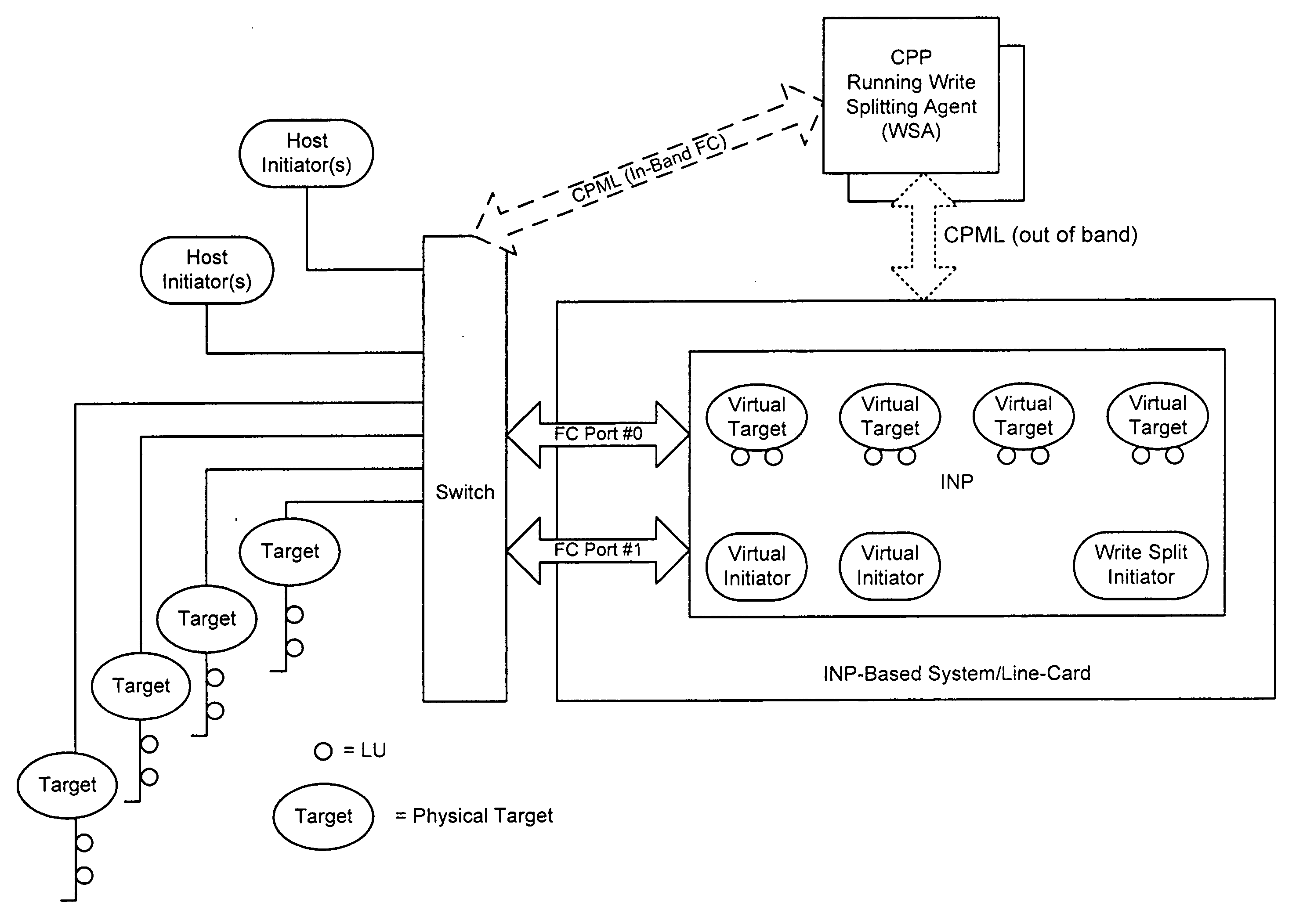
[0010] From a virtual domain perspective, the goal is to emulate the physical domain. The overall concept is to map a virtual I / O to one or more physical I / O. A virtual target (vTarget) in the virtual domain is associated with one physical port in the physical domain. Each vTarget may be associated with one or more virtual LUNs (vLUNs). As noted above, each vLUN includes one or more vExtents. The vLUNs map I / O requests, which may span two or more vExtents, to physical I / O. Each vExtent may point to a region table, which may contain one or more entries and effectively breaks up the memory represented by the vExtent into small regions. Each entry may contain a pointer to a region representing a portion of a pExtent, and attributes (e.g. read / write, read only, no access) for that region. In general, region tables provide finer granularity of control over the vLUN. Each vExtent may alternatively be associated with a layout. A “re-map” type layout points to a single pExtent and creates a mapping between the vExtent and a pExtent. A “mirror” type layout points to two pExtents for performing a mirroring function. A “striping” type layout points to two or more pExtents for performing a striping function.
[0022] Block copy copies data from one physical disk to another physical disk without involving the host software. This is typically used for data migration or snapshots, when data is copied from one disk to another disk. The block copy function is called as part of that migration or snapshot process. Block copy is normally performed between two separate devices. However, there are occasions when a block copy is attempted between two blocks that are actually part of the same target or same device. This can occur when repeated carving of the disks occurs across volumes. So it may appear that a block copy is being performed from one volume to another, when in fact the copy is being attempted within the same volume. When this occurs, read and write request can clash, and remain unresolved and waiting in both directions, resulting in deadlock. However, the block copy operation referred to above avoids deadlock.
[0026] Using the virtualization structure described above, volumes can be created in a hierarchical manner by mapping them to hierarchical extents. Hierarchical mode allows the creation of maps of various vDisks on top of vDisks. The layout tables may point to another vDisk instead of the pExtents. The hierarchy is traversed, going through multiple layers of vDisks, until a pExtent is eventually reached. The advantage of hierarchical volumes is that it makes partner applications simpler to write. For example, if it is desired to create a block copy of a vDisk, it is not necessary to get into the details of each physical layout and set permissions. Instead, a vDisk can be placed above it, regions and permissions can be created on this higher level vDisk, and a virtual block copy can then be performed on the lower vDisk using what amounts to a virtual command. The lower level details within the lower vDisk need not be managed. Similarly, if writing to a mirror, multiple writes to each pDisk are not necessary, because one write will take care of it.

Problems solved by technology

This leads to huge amounts of functionality resident on one piece of hardware and / or software.
This results in slower performance of data functions.

Method used


Image

  • Apparatus for performing storage virtualization
  • Apparatus for performing storage virtualization
  • Apparatus for performing storage virtualization

Examples


Embodiment Construction

[0077] In the following description of preferred embodiments, reference is made to the accompanying drawings which form a part hereof, and in which it is shown by way of illustration specific embodiments in which the invention may be practiced. It is to be understood that other embodiments may be utilized and structural changes may be made without departing from the scope of the preferred embodiments of the present invention.

Split-Path Architecture

[0078] Embodiments of the invention are directed to the splitting of storage applications and functions into a CP component and a DP component.

[0079]FIG. 1a is a diagram detailing a model of such a bifurcation of functions and applications. In this view, the reads and writes (such as Small Computer System Interface (SCSI) operations) are handled entirely in the DP. The application intelligence and management functions reside in the CP. In this manner, the items in the CP are responsible for discovery, configuration, and exception handli...


PUM


Abstract

The splitting of storage applications and functions into a control path (CP) component and a data path (DP) component is disclosed. Reads and writes may be handled primarily in the DP. The CP may be responsible for discovery, configuration, and exception handling. The CP can also be enabled for orchestrating complex data management operations such as snapshots and migration. Storage virtualization maps a virtual I / O to one or more physical I / O. A virtual target (vTarget) in the virtual domain is associated with one physical port in the physical domain. Each vTarget may be associated with one or more virtual LUNs (vLUNs). Each vLUN includes one or more vExtents. Each vExtent may point to a region table, and each entry in the region table may contain a pointer to a region representing a portion of a pExtent, and attributes (e.g. read / write, read only, no access) for that region.

Description

CROSS-REFERENCE TO RELATED APPLICATIONS [0001] This application claims the benefit under 35 USC 1.19(e) from U.S. Provisional Application No. 60 / 774,793 filed on Feb. 17, 2006, and is related to U.S. patent application Ser. No. 11 / 433,728 filed May 11, 2006, both of which are incorporated herein by reference.FIELD OF THE INVENTION [0002] This invention relates to communications between initiators and targets in a storage area network (SAN) fabric, and more particularly to the splitting of such communications into a control path (CP) for controlling the communication flow, and a data path (DP) for enabling the communication flow at or near wire speeds. BACKGROUND OF THE INVENTION [0003] Traditional storage applications have been monolithic systems, running all aspects of storage applications and analysis on a single processor. This leads to huge amounts of functionality resident on one piece of hardware and / or software. [0004] Conventional systems are monolithic in that they did not ...

Claims


Application Information

Patent Timeline
Patent Type & Authority Applications(United States)
IPC IPC(8): G06F12/06
CPCG06F3/067G06F11/1435G06F3/0635G06F11/2033G06F3/0613H04L45/62G06F2201/84G06F11/201G06F11/2005G06F3/0607G06F3/0664
Inventor RUPANAGUNTA, SRIRAMBHIDE, PARAG
Owner AVAGO TECH INT SALES PTE LTD
Learn More