

Engine reversing and timing control mechanism in a heat regenerative engine
- Summary
- Abstract
- Description
- Claims
- Application Information
AI Technical Summary
Benefits of technology
Problems solved by technology
Method used
Image

Examples
Embodiment Construction
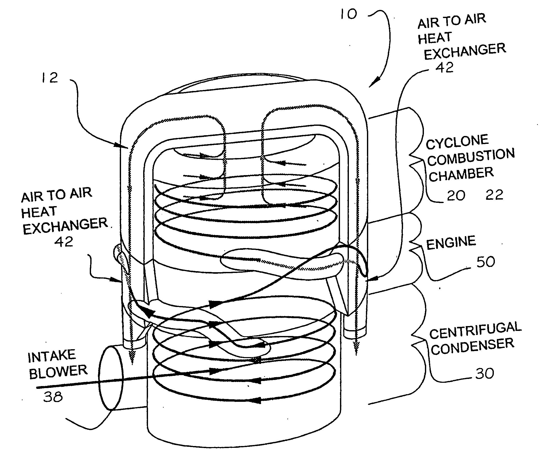
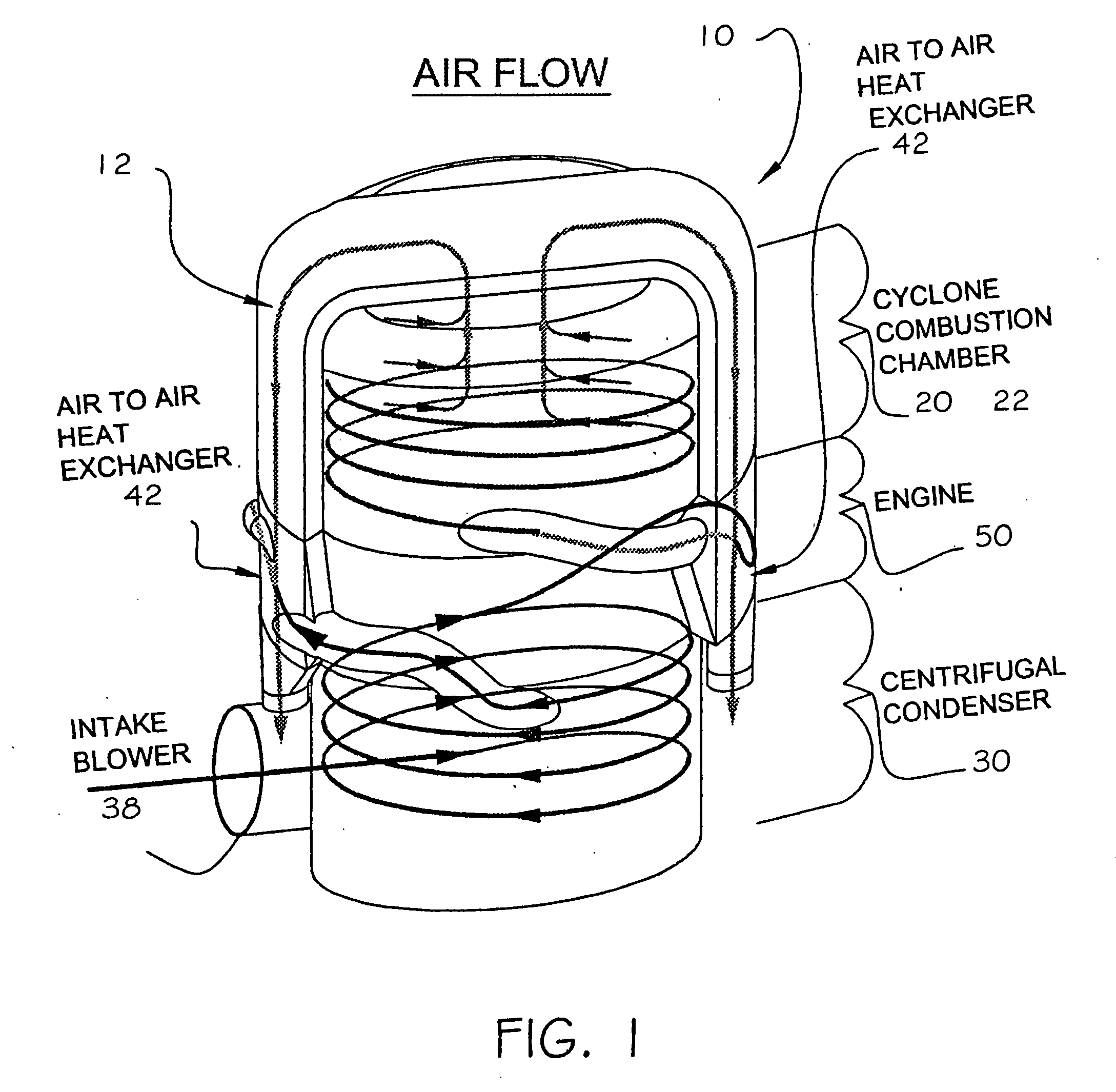
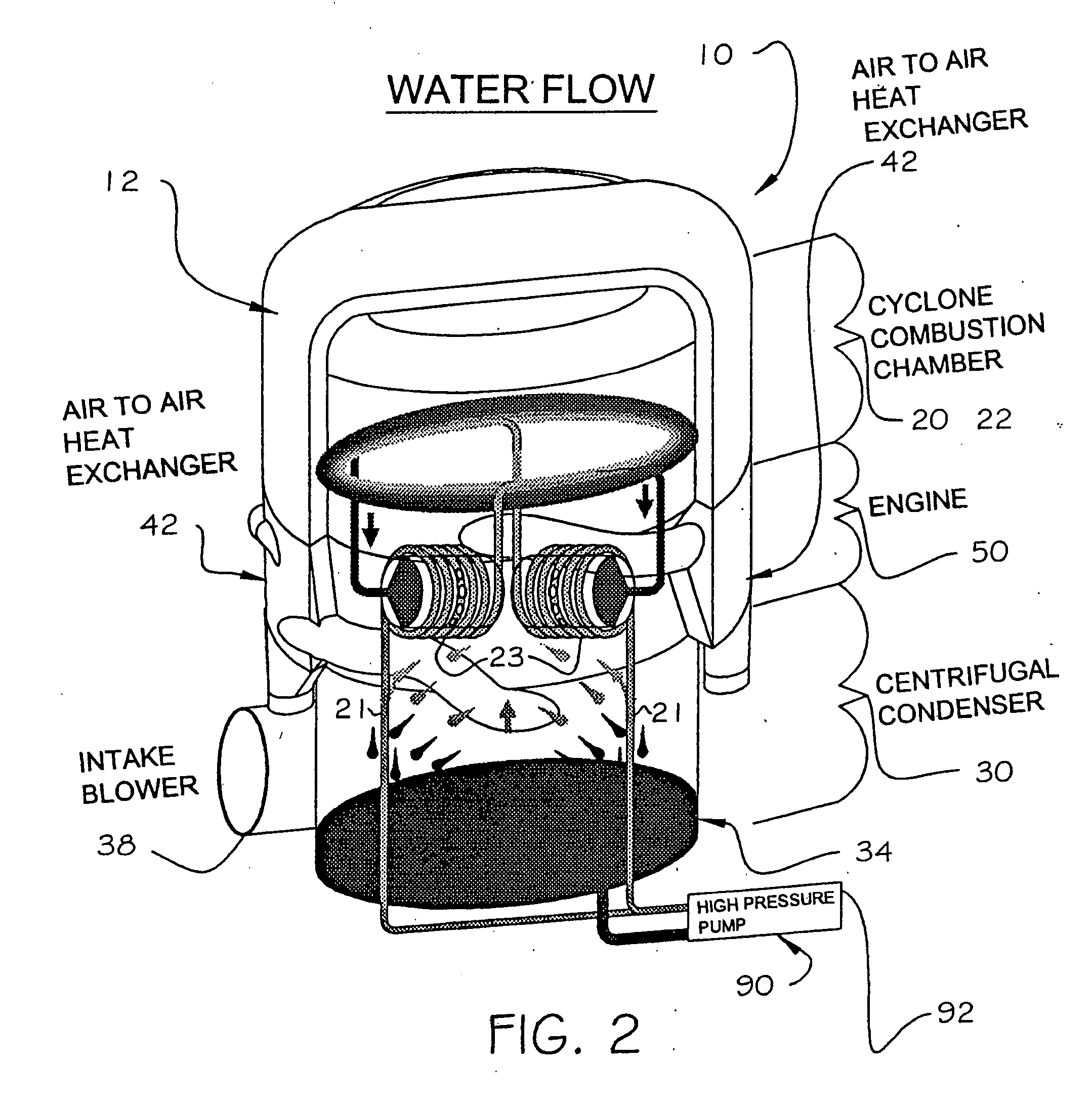
[0031] The present invention is directed to a reversing and timing control mechanism for an engine. Referring initially to FIGS. 1 and 2, an example of the engine 10 includes a steam generator 20, a condenser 30 and a main engine section 50 comprising cylinders 52, valves 53, pistons 54, push-rods 74, crank cam 61 and a crankshaft 60 extending axially through a center of the engine section.
[0032] In operation, ambient air is introduced into the condenser 30 by intake blowers 38. The air temperature is increased in two phases before entering a cyclone furnace 22 (referred to hereafter as “combustion chamber”). The condenser 30 is a flat plate dynamic condenser with a stacked arrangement of flat plates 31 surrounding an inner core. This structural design of the dynamic condenser 30 allows for multiple passes of steam to enhance the condensing function. In a first phase, air enters the condenser 30 from the blowers 38 and is circulated over the condenser plates 31 to cool the outer su...
PUM
 Abstract
Description
Claims
Application Information