Management of a thermostat's power consumption

a technology of thermostat and power consumption, which is applied in the direction of lighting and heating apparatus, heating types, instruments, etc., can solve the problems of affecting the operation and maintenance of the proper system, the limit of the possible locations of the conventional thermostat, and the inability to re-wire the existing building to relocate the thermostat, etc., to achieve the effect of reducing the energy consumption mode, and increasing the power consumption

Inactive Publication Date: 2007-10-18
RANCO OF DELAWARE
View PDF12 Cites 456 Cited by
  • Summary
  • Abstract
  • Description
  • Claims
  • Application Information

AI Technical Summary

Benefits of technology

[0011] The thermostat further includes a controller, which enters into a reduced energy consumption mode and switches the user interface to an idle state. This includes removing power from the backlight and the displays when the proximity sensor indicates a lack of user proximity for a predetermined duration. The reduced energy consumption mode provides an additional level of power conservation and extends the battery or storage capacitor charge needed to power the user interface. Consequently, when the proximity sensor indicates user proximity, the controller exits the reduced energy consumption mode and switches the user interface to an active state, which includes applying power to the backlight and the displays. In another embodiment, the intensity of the backlight is varied based on user proximity to the thermostat. Wh

Problems solved by technology

This bundle of wires between the remote equipment and the thermostat often limits the possible locations of a conventional thermostat to areas accessible by runs of the wiring bundle.
However, there may be a need to relocate a thermostat to a different room in which a user is present more frequently than the room where the wiring terminals exist.
In most situations, re-wiring existing buildings to relocate a thermostat is not cost-effective.
In

Method used


Image

  • Management of a thermostat's power consumption
  • Management of a thermostat's power consumption
  • Management of a thermostat's power consumption

Examples


Embodiment Construction

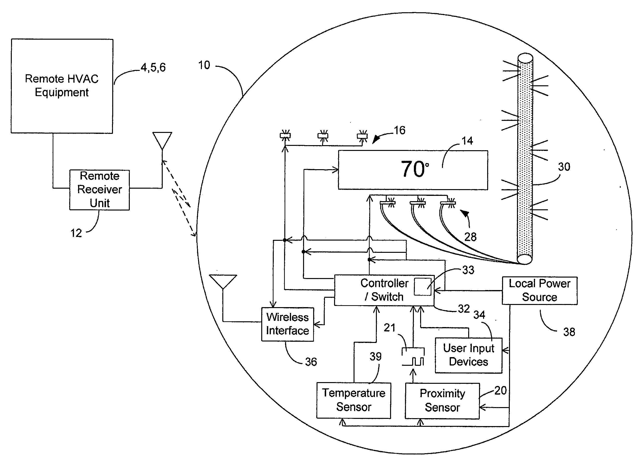
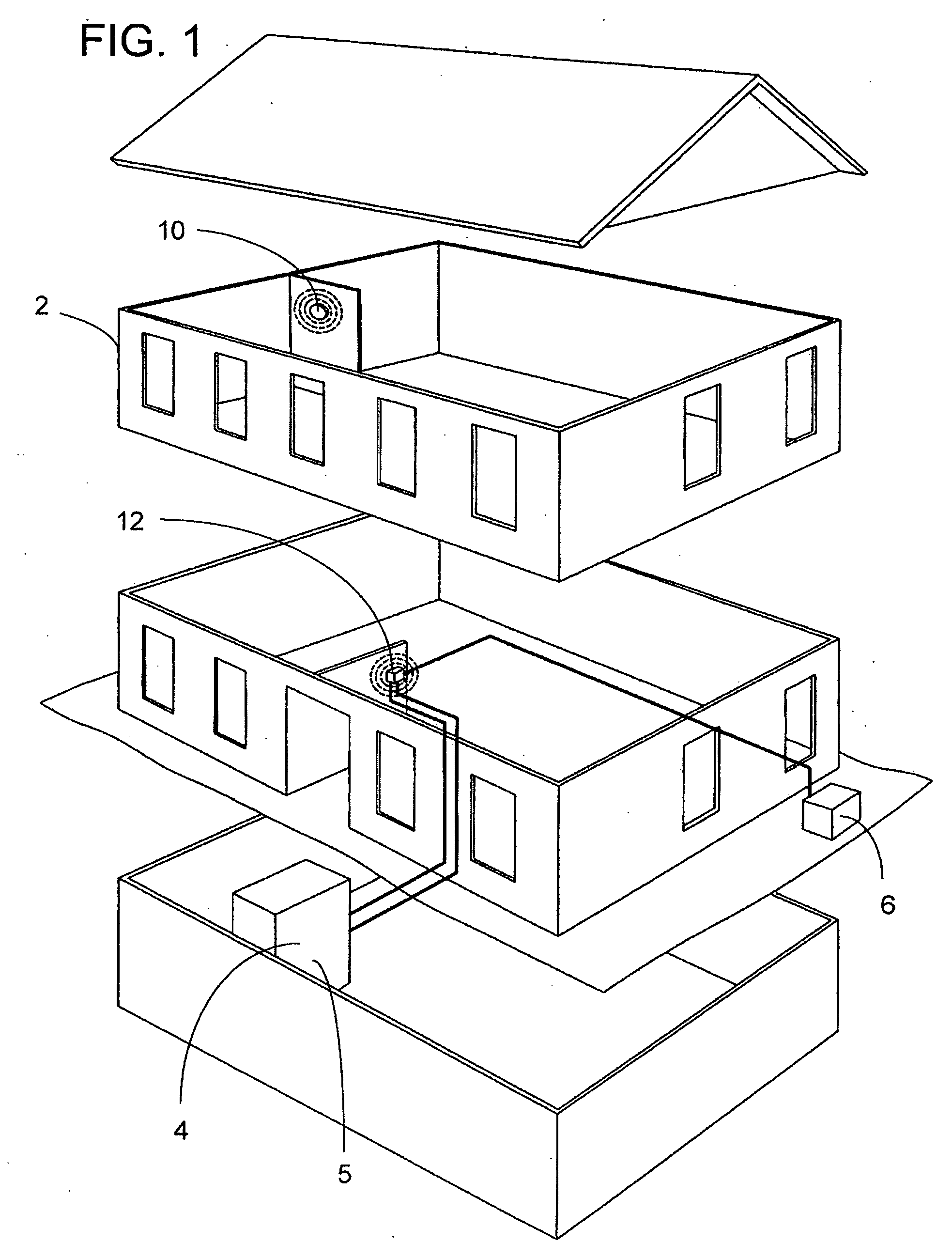
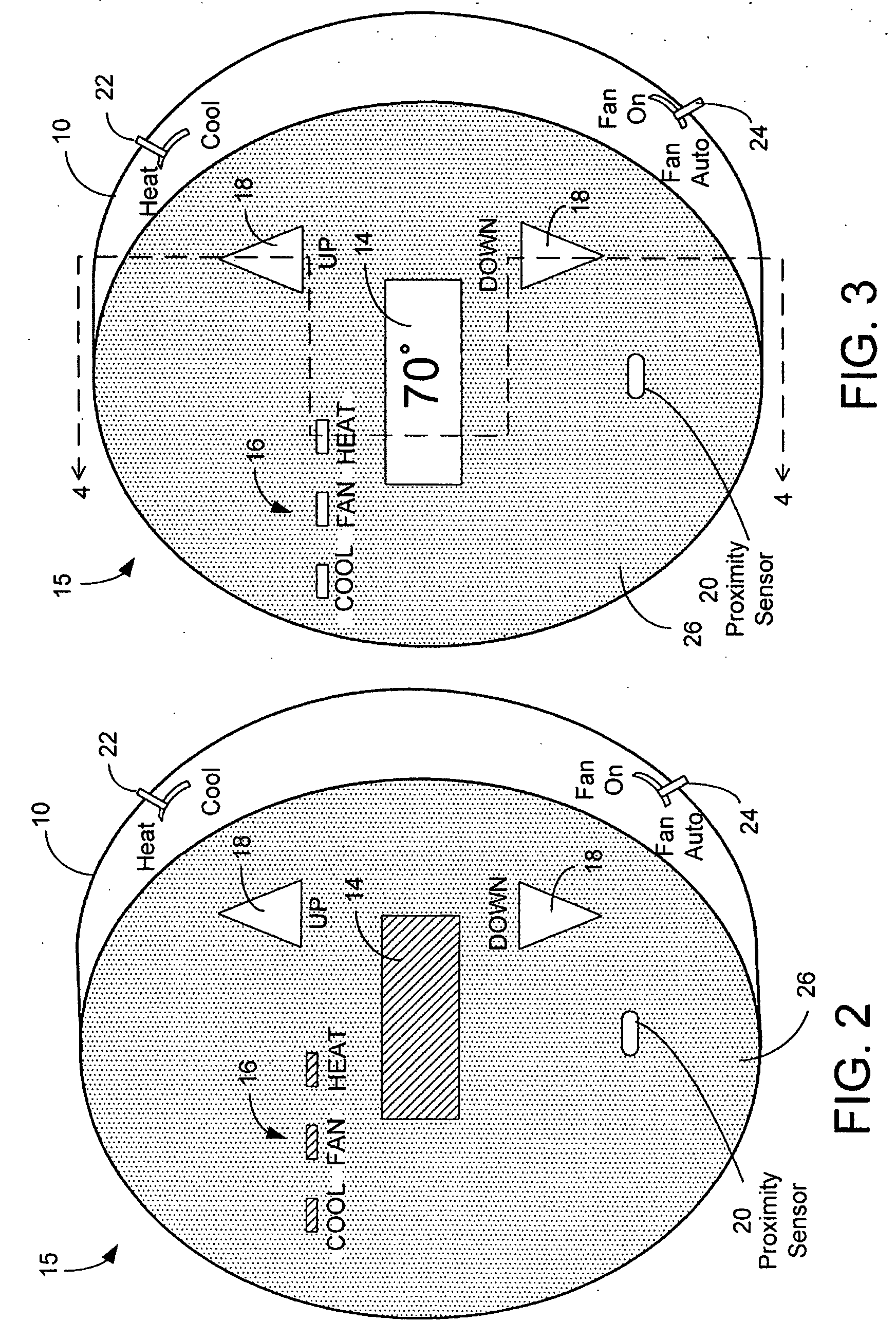
[0025] A thermostat for controlling an operating state of an HVAC system is disclosed. The thermostat includes a user interface having one or more displays, a plurality of user input devices, such as buttons, sliders, or a touch screen, and a backlight. The user interface may be powered by an energy storage device, such as a battery, for example. In another embodiment, the user interface is powered by an energy source remote from the thermostat. For example, a line voltage source can be located at the remote HVAC equipment and can charge a battery or a storage capacitor in the thermostat. In an embodiment where the thermostat includes a proximity sensor, the user interface is controlled based on a user's presence near the thermostat. In this case, the thermostat further includes a controller, or a switch, for switching the user interface to an idle state, which includes removing power from the backlight and the displays when the proximity sensor indicates a lack of user proximity fo...


PUM


Abstract

An HVAC system comprises a programmable wireless thermostat and a remote receiver unit. The thermostat includes a user interface having one or more displays, user input devices, such as buttons, sliders, or a touch screen, and a backlight. The thermostat may include a proximity sensor, wherein the user interface is controlled based on a user's presence near the thermostat. A thermostat controller enters into a reduced energy consumption mode and switches the user interface to an idle state when the proximity sensor indicates a lack of user proximity for a predetermined duration. When the proximity sensor indicates user proximity, the controller exits the reduced energy consumption mode and switches the user interface to an active state. During the reduced energy consumption mode, the user interface may be concealed when the user interface is in a housing which is transparent when backlit but is opaque otherwise.

Description

FIELD OF THE INVENTION [0001] The present invention relates to controlling the energy consuming state of an HVAC system thermostat and, more particularly, to managing the energy consuming state of a thermostat to reduce energy consumption when idle. BACKGROUND OF THE INVENTION [0002] Heating, Ventilation and Air Conditioning (HVAC) systems maintain a stable and comfortable temperature environment inside a building interior. Typical HVAC systems include a furnace unit for heating the interior during a cold season, a fan for circulating the air, an air-conditioning unit for cooling the interior during a warm season, as well as a thermostat for controlling the furnace, the fan, and the air conditioning units in order to achieve the desired ambient temperature set by a user. The heating and cooling units are usually located in an area remote from a typical living environment. A likely location for a thermostat, on the other hand, is in a room where a typical user is most likely to inter...

Claims


Application Information

Patent Timeline
IPC IPC(8): G05D23/12
CPCF24F11/0034G05D23/1905F24F2011/0075F24F11/30F24F2120/10F24F11/46F24F11/52
Inventor WAGNER, PHILLIP RYANCHAPMAN, JOHN GILMAN JR.RAO, JOSEPH P.ASHWORTH, NICHOLAS
Owner RANCO OF DELAWARE
Why Eureka
Try Eureka