Lubricant cooled integrated motor/compressor design

a technology of integrated motors and compressors, which is applied in the direction of machines/engines, liquid fuel engines, positive displacement liquid engines, etc., can solve the problems of compromising the level of energy savings at a part load, reducing the interest of consumers in other energy-efficient options, and reducing the efficiency of their efficiency, so as to prevent overboard leakage, efficient and compact

Inactive Publication Date: 2007-10-18
SULLAIR CORP
View PDF19 Cites 90 Cited by
  • Summary
  • Abstract
  • Description
  • Claims
  • Application Information

AI Technical Summary

Benefits of technology

[0016] Internal seals in the motor assembly confine the coolant and aid in channeling it to certain areas. A seal is also placed at the interface between the motor stator housing and the compressor to prevent overboard leakage. The permanent magnet motor may be classified as a Totally Enclosed Liquid Cooled (TELC) motor, as the motor is hermetically se

Problems solved by technology

However, rising energy costs and associated government programs and rebates, have increased consumer interest in other, energy efficient options.
A drawback of this design is that induction motors reach their peak efficiency at their rated speed and their efficiency drops at lower speeds, thereby compromising the level of energy savings at a part load.
In addition, the cooling requirements of AC induction motors limits the minimum operating speed which may compromise the capacity turn down.
Although there are merits to the use of gear trains, there are several penalties

Method used


Image

  • Lubricant cooled integrated motor/compressor design
  • Lubricant cooled integrated motor/compressor design
  • Lubricant cooled integrated motor/compressor design

Examples


Embodiment Construction

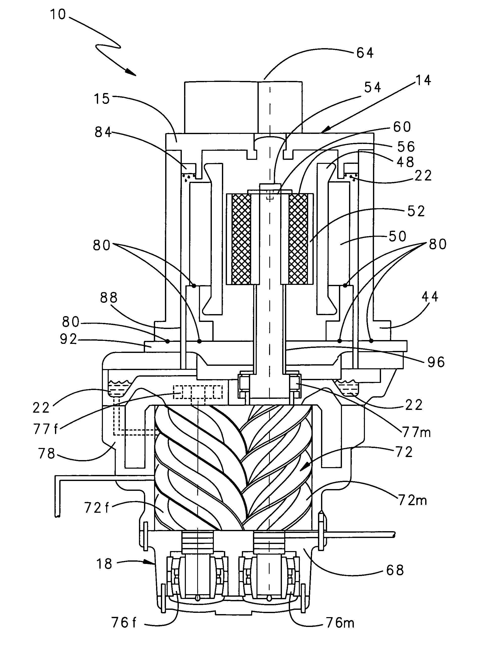
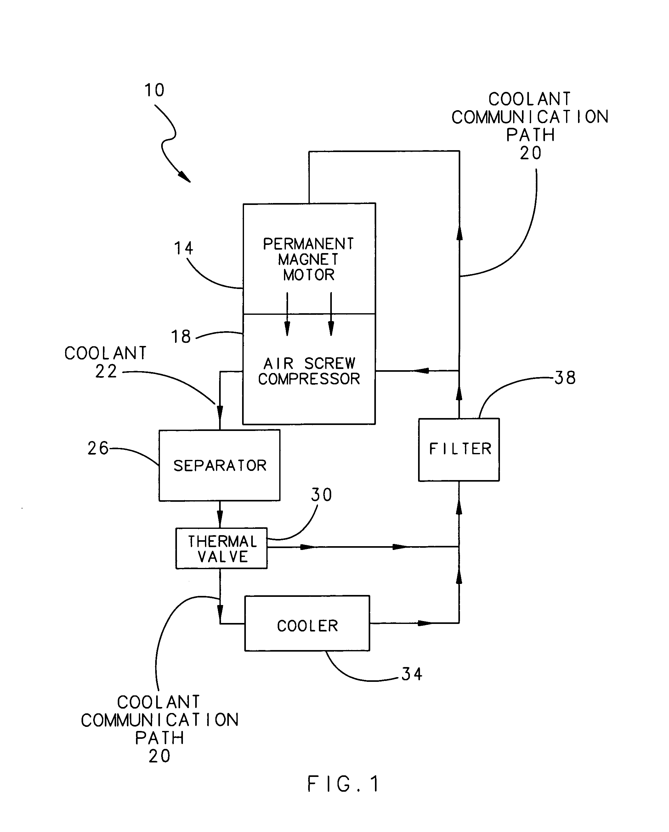
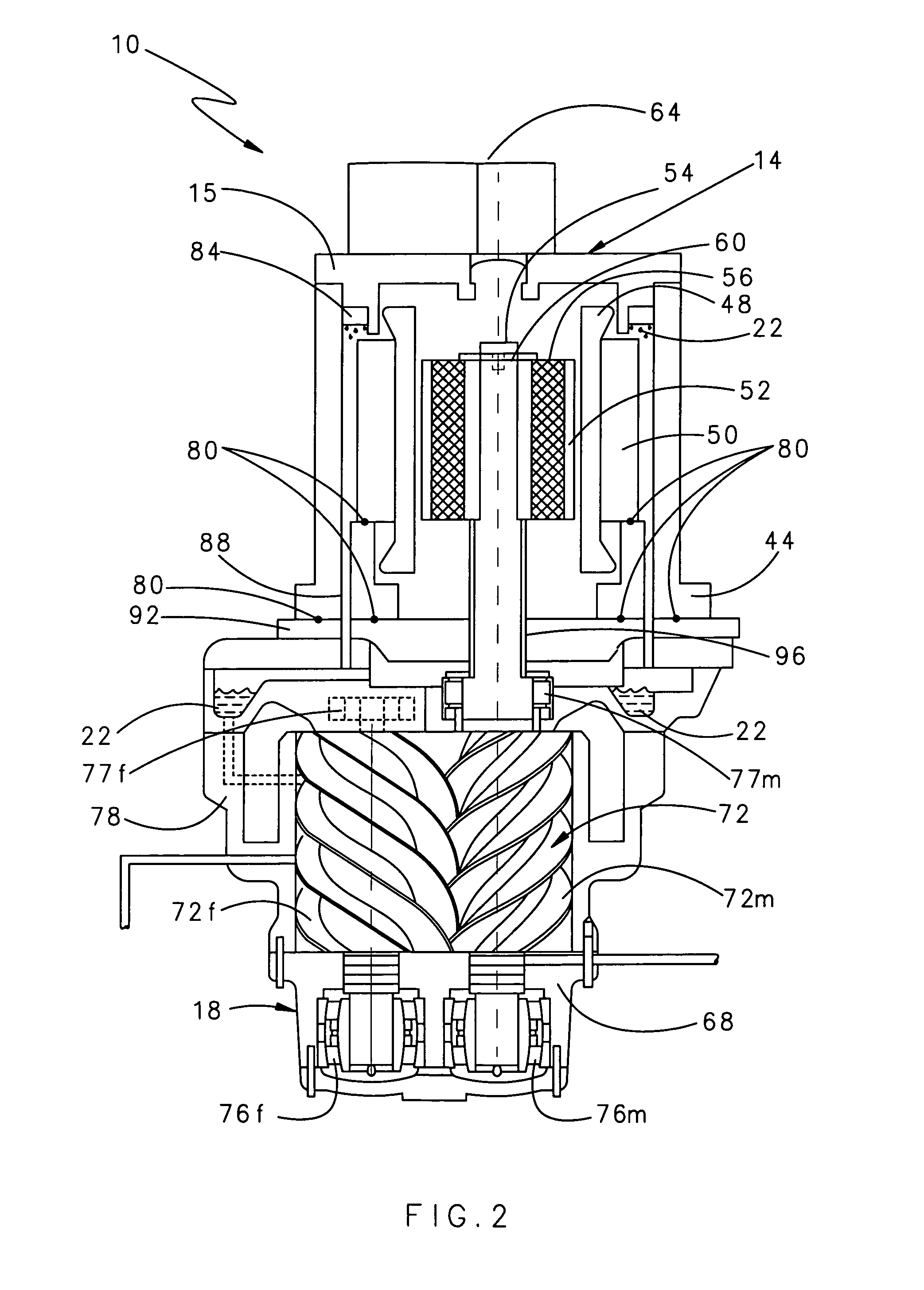
[0024]FIG. 1 illustrates a general schematic block diagram of a compressor system 10. The compressor system 10 includes a permanent magnet motor 14 mounted directly to an air screw compressor 18. The air screw compressor 18 receives a direct rotational input from the permanent magnet motor 14. The air screw compressor 18 utilizes the direct rotational input from the permanent magnet motor 14 to generate compressed air.

[0025] During air compression, the compressor system 10 produces heat which is removed from the compressor system 10 by a coolant 22. In addition, coolant 22 removes heat away from the permanent magnet motor 14 and lubricates the air screw compressor 18. The pressure differential in the system circulates coolant 22 through the compressor system 10 within a coolant communication path 20. The coolant communication path 20 circulates the coolant 22 through the air screw compressor 18 and a separator 26 which separates gas from within the coolant 22. The coolant 22 could ...


PUM


Abstract

A compressor system according to the present invention utilizes direct rotational input from a permanent magnet motor to generate compressed air. The permanent magnet motor is mounted directly to an air screw compressor. The rotational input is provided by the permanent magnet motor to the air screw compressor without a gear train. The permanent magnet motor and associated variable speed drive controls the rotational speed of the permanent magnet motor and hence the screw compressor. Differing motors may selectively mount, and provide rotational input to, the air screw compressor.

Description

BACKGROUND OF THE INVENTION [0001] The present invention relates generally to a motor for an air screw compressor and, more particularly, to a permanent magnet motor rotor mounted directly to an air screw compressor rotor. [0002] An air screw compressor includes a male and female compressor rotor supported by bearings inside a housing which rotate relative to each other to produce compressed air. Conventional air screw compressors are typically driven by a gear train which receives rotational input from an induction motor. In some applications where a variable speed drive is utilized, the air compression output is adjusted by varying the rotational speed of the motor which adjusts the compressor rotor speed. [0003] Typically, two or four pole AC induction motors drive air screw compressors and are known for their competitive pricing, high reliability, and wide service channels. However, rising energy costs and associated government programs and rebates, have increased consumer inter...

Claims


Application Information

Patent Timeline
IPC IPC(8): H02K9/20H02K9/26H02K9/00
CPCF04C18/16F04C23/008F04C29/0085H02K9/19F04C2240/52H02K7/14F04C29/045
Inventor KHARSA, JOHN E.
Owner SULLAIR CORP
Why Eureka
Try Eureka