Borehole Imaging

a technology for boreholes and wells, applied in the field of borehole imaging, can solve the problems of inability to use, and the nature of the measurement does not allow the acquisition of images,

Inactive Publication Date: 2007-10-18
SCHLUMBERGER TECH CORP
View PDF21 Cites 51 Cited by
  • Summary
  • Abstract
  • Description
  • Claims
  • Application Information

AI Technical Summary

Benefits of technology

[0020] The use of a coherent fibre bundle to obtain the image of the borehole wall allows detailed images of the formation to be obtained, the large number of small fibres at the window providing the necessary resolution to obtain images of grain structure and the like.

Problems solved by technology

Such an approach requires the presence of a transparent fluid in the well and so cannot be used in the drilling or production phase of a well in which opaque fluids are present.
The nature of the measurement does not allow an image to be obtained.

Method used


Image

  • Borehole Imaging
  • Borehole Imaging
  • Borehole Imaging

Examples


first embodiment

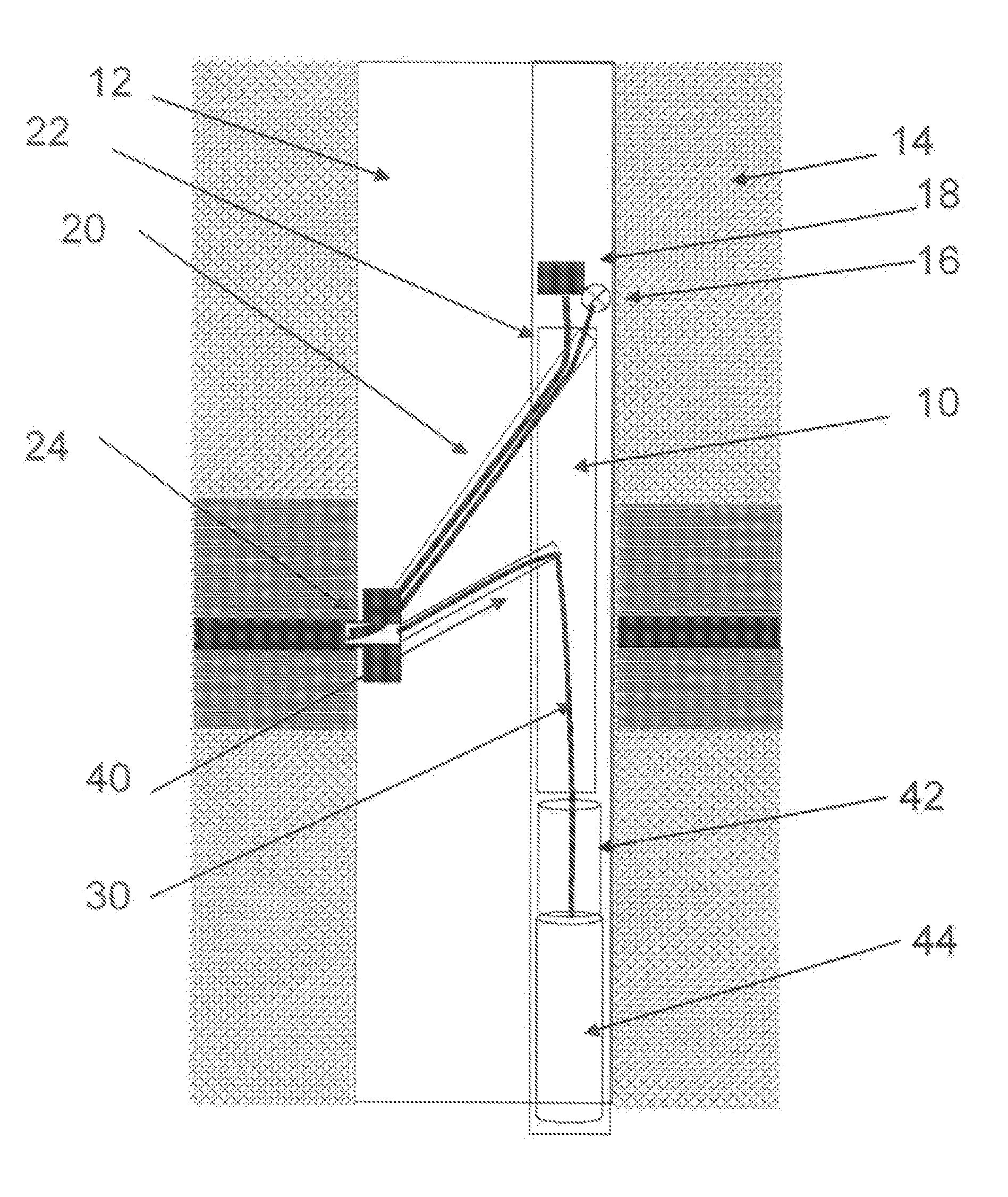
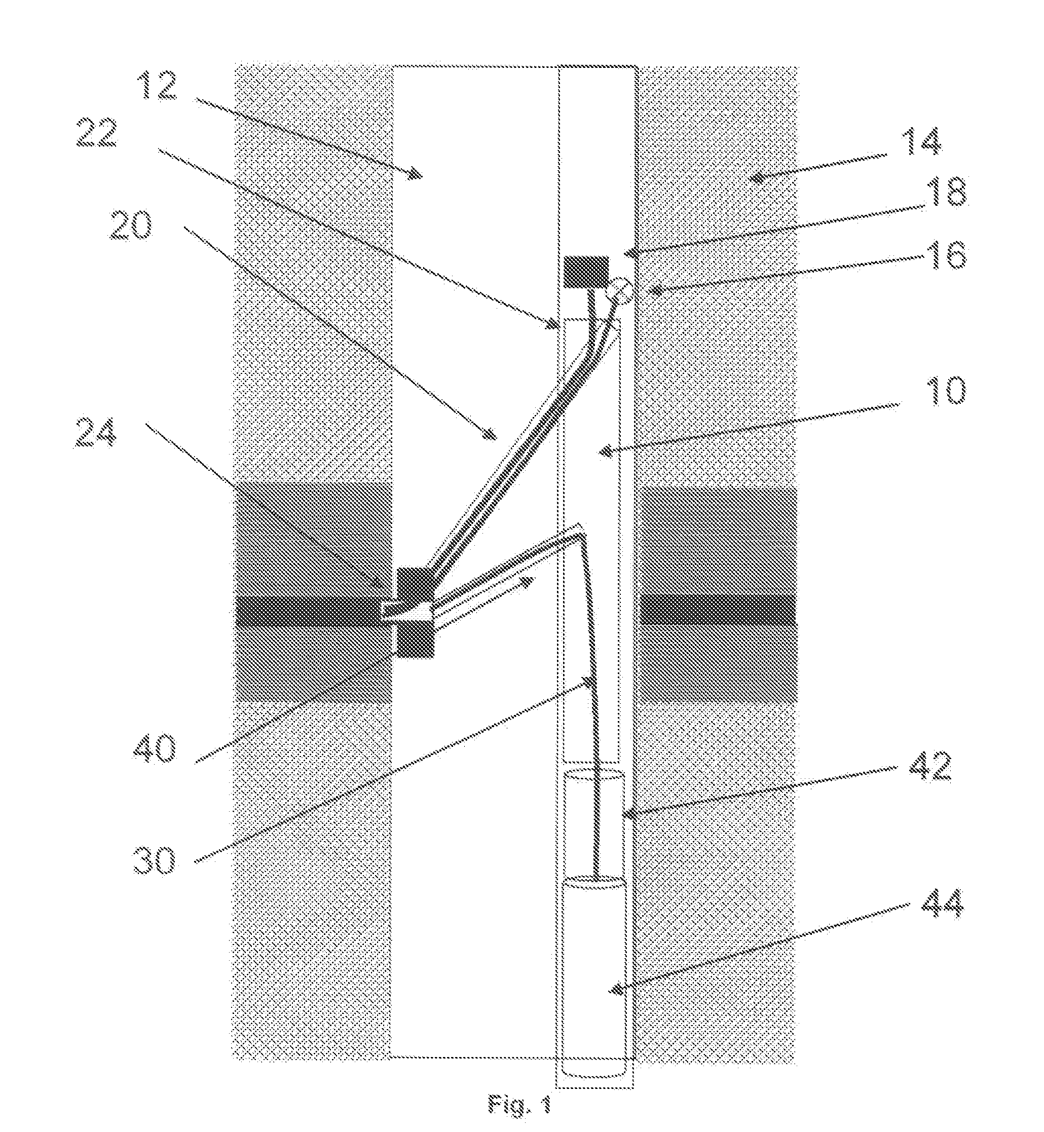
[0029] the invention is shown in FIGS. 1 and 2, and comprises a tool body 10 that is lowered into a borehole 12 that has been drilled through an underground formation 14. The tool body 10 is suspended on a wireline cable (not shown) which extends to the surface and allows the tool 10 to be lowered and raised in the borehole, and provides power and a data communication path back to the surface. Another form of conveyance applicable is coiled tubing which can also carry a cable for power and data. In this respect, tools according to the invention behave in the same manner as other logging tools.

[0030] The tool body 10 carries a light source 16 (such as a red LED, UV or IR lamp, white light lamp, laser or other such device) and an imaging device in the form of a CCD (or CMOS) camera 18.

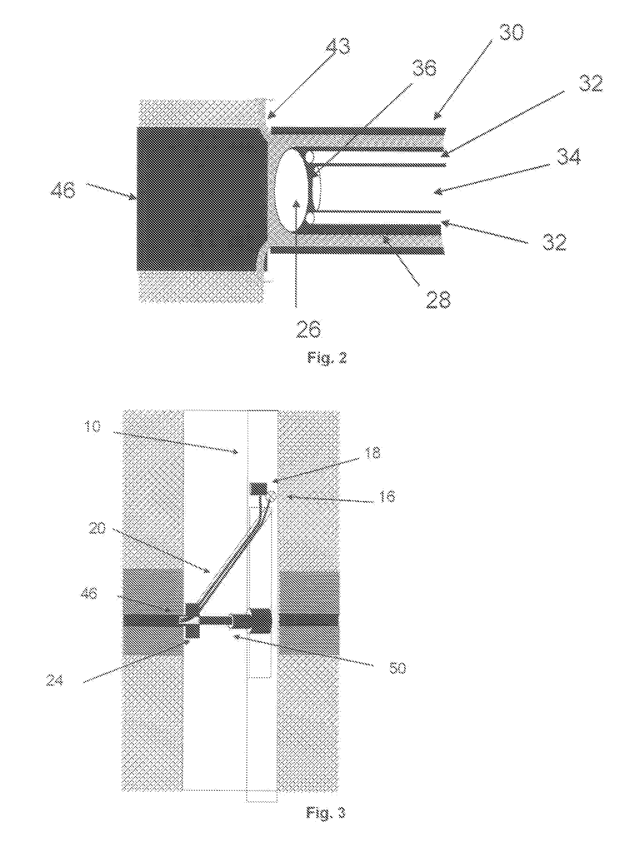
[0031] A sensor arm 20 is pivotally connected to the tool body 10 at one end 22 and carries a sensor head 24 in the form of a pad at its other end. The sensor head 24 has an optical window 26 with a foc...

fourth embodiment

[0040]FIG. 7 shows the invention. The general tool arrangement is similar to that described previously with a main tool body 110 suspended on a wireline cable 100. The tool body 110 houses a light source 116 and an electronics cartridge 126. A sensor pad 125 is mounted on the tool body 110 by means of an arm 112 and a backup arm 114 is provided to ensure that the pad 125 can be held against the borehole wall in the correct orientation. The pad carries two sensor heads 120, 122, each comprising a diamond (typically transparent, synthetic diamond), plough structure acting as a separate sensor window. The sensor heads 120, 122 have a sharp, cutting structure that allows them to cut into the formation and obtain a clear image. Each sensor head is connected to a coherent fibre bundle 130, 132 that extends to the tool body 110 along the arm and connects to the light source 116 and to a respective camera 118, 119. The two sensor heads 120, 122 are arranged to provide different levels of op...


PUM


Abstract

Apparatus for imaging the wall of a borehole drilled through an underground formation, comprising: a light source; an optical detector device such as a CCD camera; a sensor head including a window for application against the wall of the borehole, the light source being connected to the sensor head so as to illuminate the region of the borehole wall when the sensor head is applied to the wall; and an optical fibre bundle connecting the window to the optical detector device so as to pass optical signals from the wall to the optical detector device; wherein the optical fibre bundle comprises a coherent bundle, each fibre of the coherent bundle providing one pixel of a two-dimensional, multi-pixel image of the borehole wall.

Description

TECHNICAL FIELD [0001] This invention relates to apparatus and techniques for obtaining high-resolution images of underground formations through which a borehole is drilled. BACKGROUND ART [0002] A number of techniques have been previously proposed for obtaining images of a formation at the wall of a borehole. Such images are useful in understanding the geology and lithology of the formation. Such information can be particularly useful when drilling boreholes such as oil and gas wells since it can help to identify the presence of desirable fluids and provide information allowing effective completion of the well. [0003] The use of video technology for inspecting the inside of boreholes is known. An example can be found in U.S. Pat. No. 5,790,185. This technique is typically used to obtain images of large scale structure in the borehole, for example the state of casing or perforations. Such an approach requires the presence of a transparent fluid in the well and so cannot be used in t...

Claims


Application Information

Patent Timeline
Patent Type & Authority Applications(United States)
IPC IPC(8): G01V8/10E21B33/08G02B6/04E21B47/00
CPCG01V8/02E21B47/0002E21B47/002
Inventor VESSEREAU, PATRICKCHEUNG, PHILIP
Owner SCHLUMBERGER TECH CORP
Why Eureka
Try Eureka