For example, damage to the surface or probe may occur if the probe deflection exceeds a maximum limit.
With conventional SFM's, this detection circuitry generally obstructs an optical view of the probe positioned over the sample.
1. In an SFM, the probe normally wears out and must be replaced after several samples have been scanned. Moreover, it is often desirable to change probes between samples to avoid contaminating the surface of a new sample with material accumulated on the tip from a previous sample surface. With the type of deflection sensor described above, the
laser beam must be precisely directed to a very small area, on the order of 20 microns wide, on the back of the
cantilever. Each time the
cantilever is replaced, the
laser beam must be readjusted so that it strikes the same position. Aligning the deflection sensor is a time-consuming procedure and typically requires a very precise position stage. For example, scanning a sample might take 30 minutes, and repositioning the
laser spot might take an additional 15 minutes. Thus, a large portion of the time spent on a sample must be used to realign the deflection sensor after the probe has been replaced.
2. Different preamplification circuitry is required to amplify either the
signal from the deflection sensor in an SFM or the tunneling currents from the tip in an STM. These preamps must be located in the head, close to the source of their respective signals, to reduce
noise pickup. Likewise, SFMs and STMs typically require different probes, also located in the head. In the prior art arrangements, a head is dedicated either to an SFM or to an STM. Consequently, the head must be disengaged and replaced in order to switch between SFM and STM operating
modes. This is a
time consuming procedure. Moreover, each head is an expensive component.
3. A bi-
cell PSPD is typically used in the deflection sensor of an SFM to detect changes in light position caused by
cantilever deflection. The sensitivity of bi-cells to these changes depends nonlinearly on the initial light position. Sensitivity is greatest when the light strikes the center of the PSPD, thereby producing a zero initial
signal. As the light position moves off-center center (i.e., an initial
signal offset is present), sensitivity drops. If the initial offset is too large, the bi-
cell cannot function, since light strikes only one of the cells. This nonlinear
position response is further adversely affected by intensity variations across the width of the
light spot. To minimize these effects, frequent and time-consuming adjustments to zero the initial signal offset are necessary before running the
microscope and each time a probe is changed.
4. The coarse x, y stage in an SPM is often a stacked structure which has at least three levels: a fixed base, a y stage, and an x stage. This configuration has a relatively large mechanical loop, i.e., thermal and mechanical displacements in these individual stages are cumulative and can affect the spacing between the probe and the sample. These displacements are a significant source of
noise in the data. A configuration with a large mechanical loop may also be unstable.
5. Piezoelectric scanners inherently exhibit nonlinear behavior which includes
hysteresis (where the
scanner position for a given control
voltage is a function of
past history of movement),
creep (where the
scanner position gradually drifts in response to an applied
voltage), and nonlinear response (where the
scanner position is a nonlinear function of applied
voltage). In addition, bending of a
piezoelectric tube scanner is inherently associated with its
lateral movement and causes it to tilt. These nonlinear effects contribute undesirably to the data image and require some means for scan correction. U.S. Pat. No. 5,051,646 describes a method to correct for these nonlinearities by applying a
nonlinear control voltage to the piezoelectric scanner. However, this method is "open loop", i.e., it does not use feedback and has no means to determine and correct the actual scanner motion due to the applied nonlinear input signal. Application Ser. No. 07 / 766,656, filed Sep. 26, 1991, which is incorporated herein by reference, describes a method of correcting for nonlinearities in the x, y lateral motion of the scanner that is "
closed loop", i.e., it does not use feedback. However, the method does not take into account the bending of a
piezoelectric tube scanner, which causes tilt.
6. In typical SPMs the problem of
hysteresis requires that each line of data in the
raster scan be collected in the same direction, since data collected in the reverse direction includes the effects of
hysteresis. As a consequence, each line of the
raster scan must be traversed twice--once to collect data and once to return along the same path (or vice versa). The length of time necessary to generate an image is thus significantly greater than what it might be without hysteresis effects. Moreover, hysteresis problems prevent the use of data collected in the forward scan of a line to adjust the scan parameters before generating an image from scanning the line in the reverse direction.
7. Another source of error in the data image arises due to the thickness of the sample. As a
piezoelectric tube scanner bends to thereby produce a lateral motion of a sample (or probe) mounted on it, the sample (or probe) moves in an arc-shaped path. As the thickness (vertical dimension) of the sample increases, a given input signal to the piezoelectric tube scanner therefore produces a larger
horizontal translation of the surface of the sample.
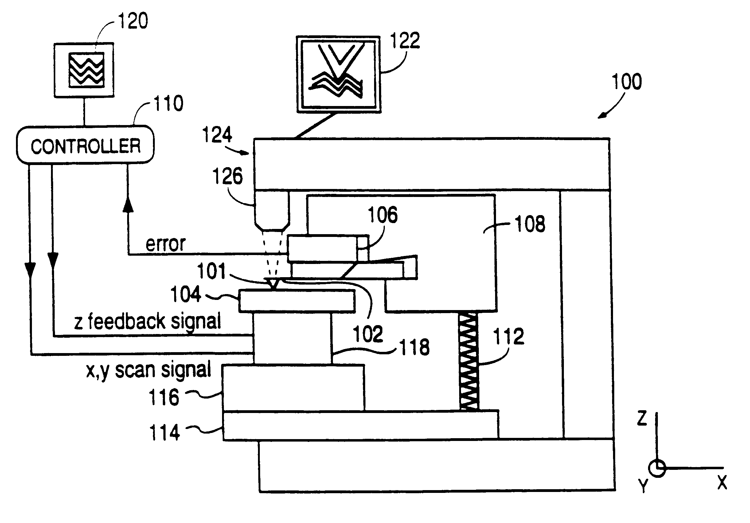
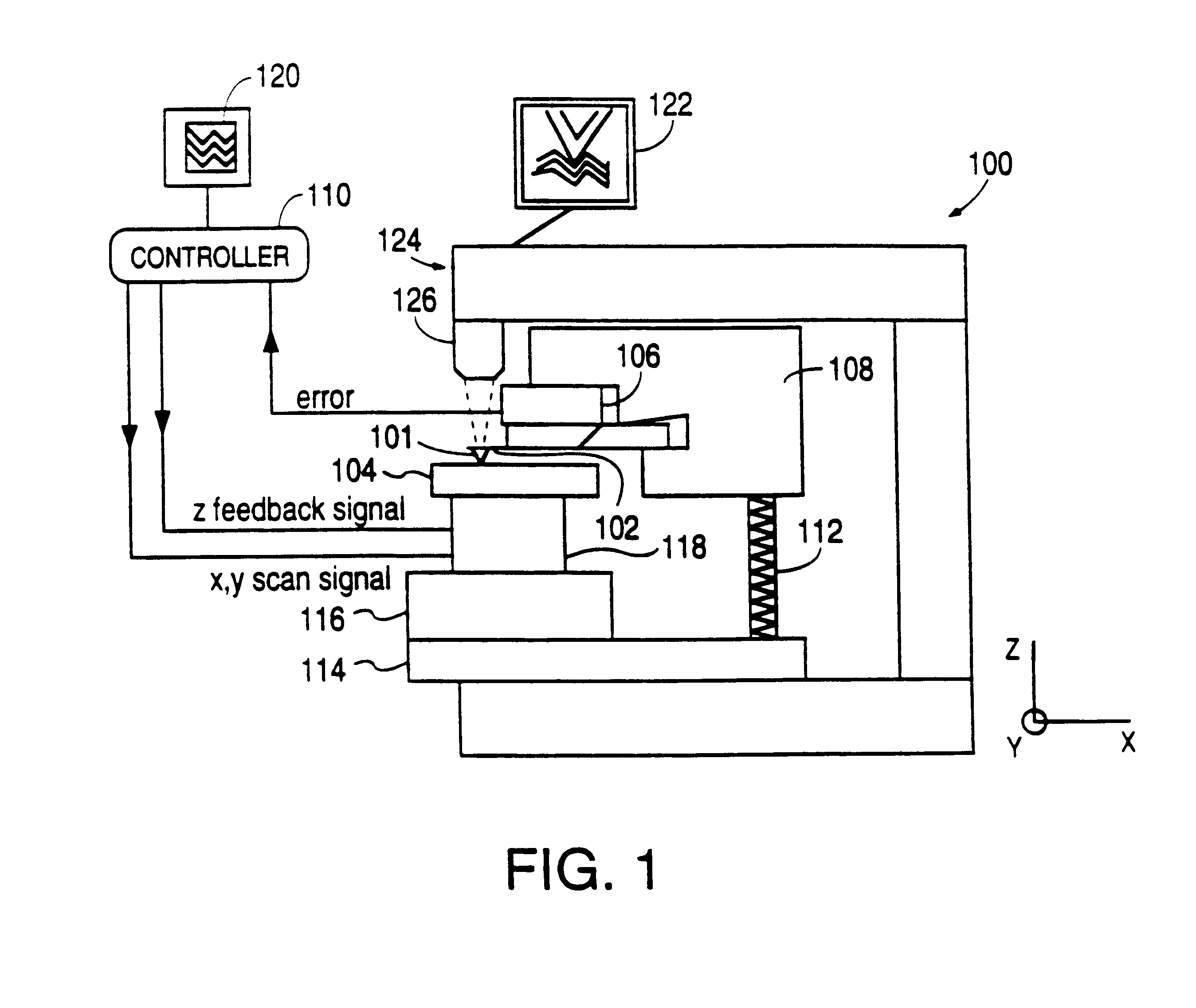
8. In order to position the sample relative to the probe, it is useful to have both a coaxial (on-axis) and oblique view of the same using an
optical microscope. These views provide means to monitor fine positioning of the sample relative to the probe. The coaxial view assists in positioning the probe over the feature of the sample to be measured. The oblique view permits accurate adjustment of probe orientation (for instance, cantilever tilt) relative to the sample surface. Conventional SPMs provide both these features; however, they are provided in two separate, manually operated microscopes, which are unwieldy to use. Obtaining these dual views is thus inconvenient.
9. In prior art SPMs the piezoelectric tube scanner cannot be operated at a rate greater than its resonant frequency. Above its resonant frequency, the response of the scanner to an input voltage signal is greatly reduced and
out of phase with the input signal.
Prior art SPMs do not permit the adjustment of scanning parameters such as scanning rate or probe path in response to topographical features encountered by the probe.
As noted above, this error results from the bending of the piezoelectric tube scanner as its free end, holding the sample, is displaced laterally in response to the input voltage.
This significantly shortens the
iteration process required to achieve optimal 3-dimensional rendering.

