
Device and method for the contactless measurement of at least one curved surface

a technology of contactless measurement and curved surfaces, applied in measurement devices, instruments, using optical means, etc., can solve the problems of limited installation space of measurement heads in one, and achieve the effect of optimal measurement properties of optical systems and small apertures

Inactive Publication Date: 2007-10-18
PRECITEC OPTRONIK GMBH
View PDF6 Cites 7 Cited by
  • Summary
  • Abstract
  • Description
  • Claims
  • Application Information

AI Technical Summary

Benefits of technology

The present invention relates to a device and method for measuring surfaces with a high degree of accuracy. The device has a measurement head with a cross section that is narrow in at least one space direction and has optimal measurement properties, such as high light sensitivity and large resolving power. The optical system is designed to have a reduced aperture in the space direction in which the optical axis is perpendicular to the surface being measured. This allows for optimal measurement properties while maintaining a small aperture. The measurement heads can be moved relative to the surface to measure it scanner fashion. The device can also be used to determine the thickness of layers in transparent bodies, such as glass or plastic bottles. The method involves aligning the optical system perpendicular to the surface and using a small aperture in the space direction to measure with the same optimal properties.

Problems solved by technology

The installation space for the measurement heads is however often limited in one space direction, particularly when a multiplicity of measurement heads are to be arranged in sequence with a small spacing.

Method used


Image

  • Device and method for the contactless measurement of at least one curved surface
  • Device and method for the contactless measurement of at least one curved surface
  • Device and method for the contactless measurement of at least one curved surface

Examples


Embodiment Construction

[0026]While this invention is susceptible of embodiment in many different forms, there is shown in the drawings and will herein be described in detail one or more embodiments with the understanding that the present disclosure is to be considered as an exemplification of the principles of the invention and is not intended to limit the invention to the embodiments illustrated.

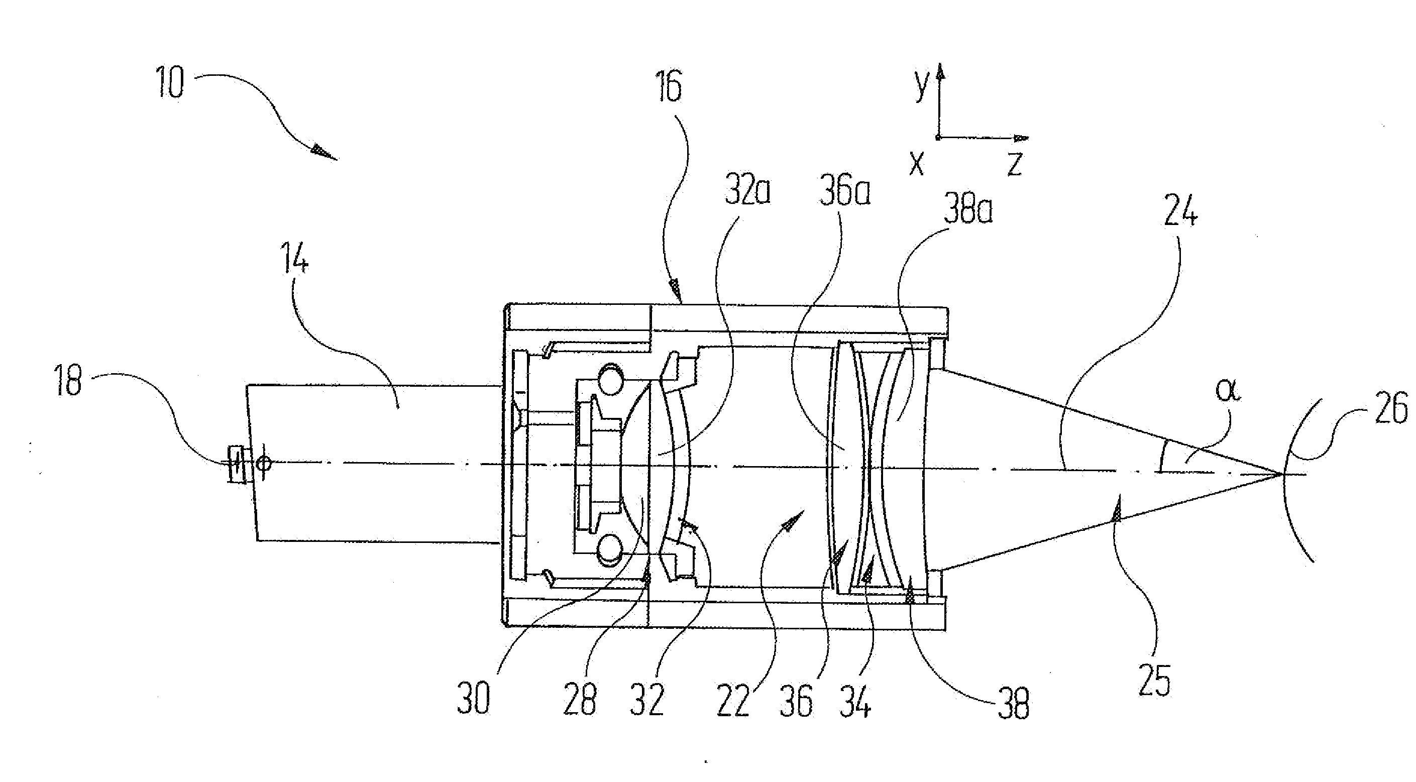
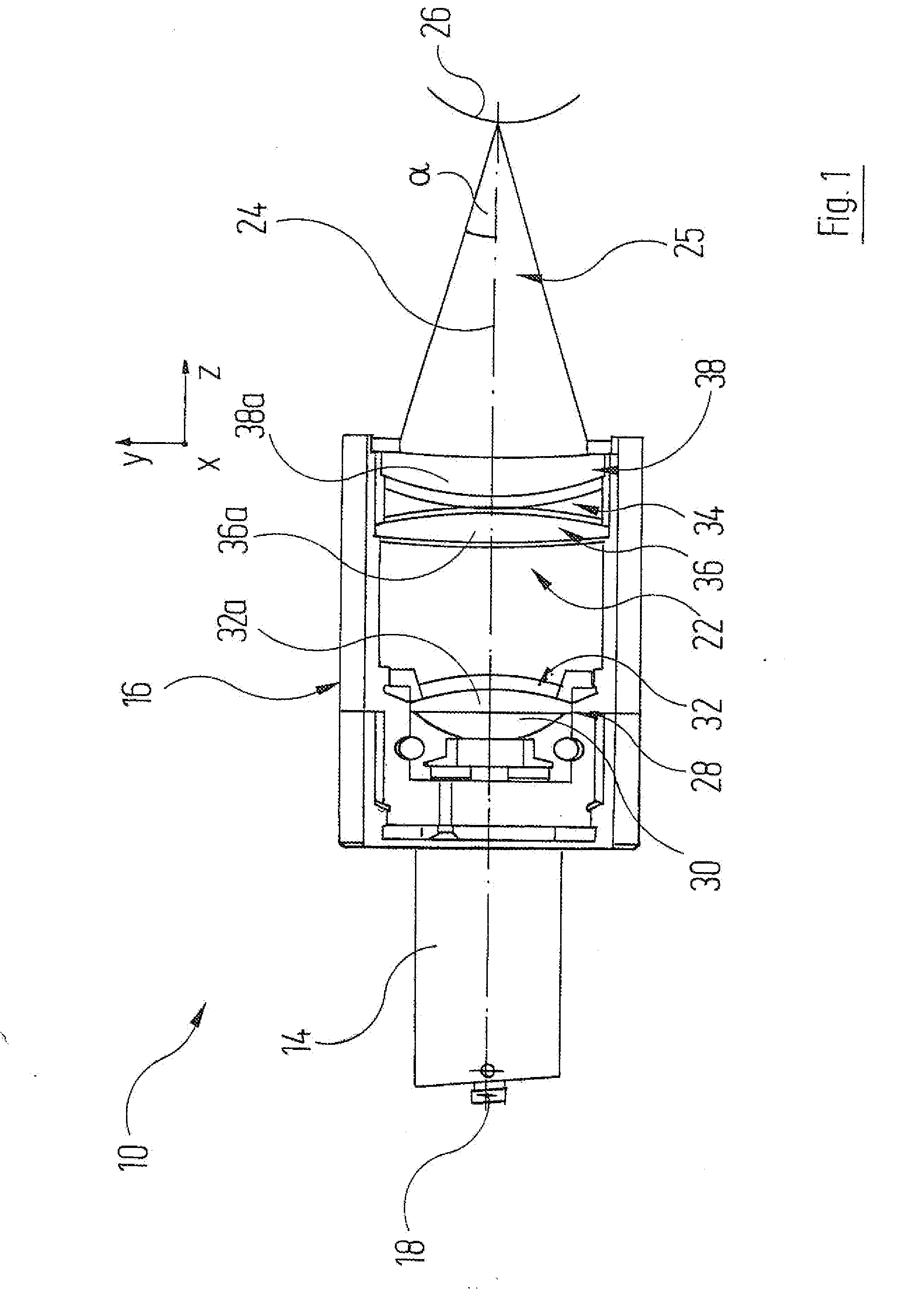
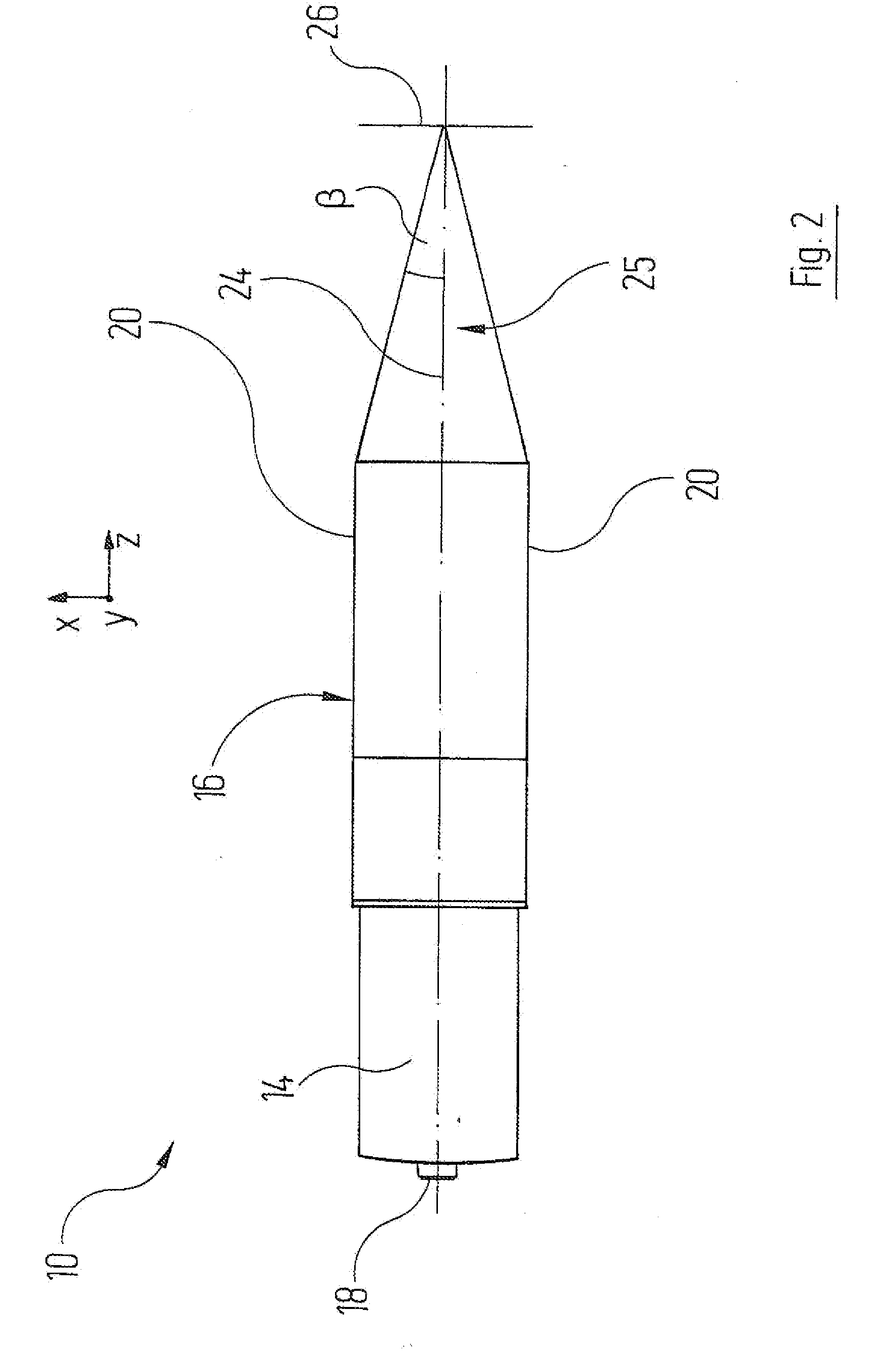
[0027]FIGS. 1 to 3 show an elongate measurement head, provided overall with the reference numeral 10, of a measurement head arrangement as shown in FIGS. 4 and 5 of a device (otherwise not represented) for contactless determination of the wall thickness of a glass cylinder 12, which is represented in FIG. 5.

[0028]The measurement head 10 is connected via a multimode optical waveguide (not shown) to a known light source for generating light with a continuous spectrum. The optical waveguide leads to a circular-cylindrical light guide connector body 14 on the rear end side of a housing 16 of the measurement head 10, ...


PUM

PropertyMeasurementUnit
lengthaaaaaaaaaa
lengthaaaaaaaaaa
outer diameteraaaaaaaaaa

Abstract

A device and a method for the contactless measurement of at least one curved surface. The device comprises at least one light source for generating light with a continuous spectrum, and a light exit face assigned to the light source. It furthermore has at least one measurement head having an optical imaging system with chromatic aberration for imaging the light exit face into wavelength-dependent focal planes, and an optical spectral instrument by which it is possible to record the spectral intensity distribution of light which is directed through the optical system onto the surface to be measured and is reflected therefrom. The device is furthermore equipped with an evaluation unit by which a distance between the optical system and the surface can be assigned to each wavelength at which the intensity distribution recorded by the optical spectral instrument has a local maximum. The surface to be measured is plane in one space direction. The optical axis of the optical system is perpendicular to the surface in this space direction. Furthermore, the width of the optical system is reduced perpendicularly to its optical axis in this space direction.

Description

RELATED APPLICATIONS[0001]The present invention claims the benefit of the filing date of German Patent Application, Serial No. 10 2006 017 400.3, filed Apr. 13, 2006; the content of which is incorporated by reference herein.TECHNICAL FIELD[0002]The present invention relates to a device for the contactless measurement of at least one curved surface, having at least a light source for generating light with a continuous spectrum, a light exit face assigned to the light source, a measurement head having an optical imaging system with chromatic aberration for imaging the light exit face into wavelength-dependent focal planes, an optical spectral instrument, by which it is possible to record the spectral intensity distribution of light which is directed through the optical system onto the surface to be measured and is reflected therefrom, and an evaluation unit by which a distance between the optical system and the surface can be assigned to each wavelength at which the intensity distribu...

Claims


Application Information

Patent Timeline
Patent Type & Authority Applications(United States)
IPC IPC(8): G01B11/24
CPCG01B11/24
Inventor MICHELT, BERTHOLDKUNKEL, MATTHIASDIETZ, CHRISTOPH
Owner PRECITEC OPTRONIK GMBH
Learn More