Small Field Intensity Modulated Radiation Therapy Machine

a radiation therapy machine and intensity modulation technology, applied in radiation therapy, medical science, therapy, etc., can solve the problems of limited accuracy of current tomotherapy systems, and achieve the effect of precise control of dose patterns, shortening the distance, and reducing the distan

Active Publication Date: 2007-10-18
WISCONSIN ALUMNI RES FOUND
View PDF4 Cites 46 Cited by
  • Summary
  • Abstract
  • Description
  • Claims
  • Application Information

AI Technical Summary

Benefits of technology

[0010] The present inventors have recognized that the benefits of Tomotherapy can be expanded through the use of a Tomotherapy machine having a shortened source to rotation axis distance. First, by shortening this distance, the gantry may be made sufficiently compact to be maneuvered to be positioned around the particular body part, for example, the breast requiring treatment, thus eliminating the need for generalized exposure to the patient's torso. Second, by reducing this distance, narrower rays are naturally created without changing the shutter structure. The improved resolution made possible, is particularly well-suited for treatment of tumors in the head or the breast, where more precise control of dose patterns can be beneficial and meaningful because patient motion may be more readily controlled in these parts of the body.
[0014] It is thus an object of at least one embodiment of the invention to provide a system that may provide support that is well adapted to treatment of particular portions of the anatomy.
[0018] It is thus another object of at least one embodiment of the invention to provide a simple, self-contained system for treating brain tumors that allows the patient to rest in a comfortable supine position.
[0024] It is thus another object of at least one embodiment of the invention to provide a simple modulator mechanism that may work within the compact space of the present invention. It is a further object of the invention to allow precise radiation treatment, for example near the chest wall for one breast, where conformal treatment, using multileaf collimators to outline a tumor shape, is not practical because of the inability to move shutters into the space occupied by the patient's chest wall.
[0032] It is another object of at least one embodiment of the invention to provide a low inertia, simplified radiation source for a small field radiation therapy machine that may thus work in confined spaces.
[0037] Thus it is another object of the invention to provide increased flexibility in orienting the radiotherapy equipment with respect to the patient.

Problems solved by technology

The increased accuracy of current Tomotherapy systems is limited by physical constraints related to creating narrower occluding leaves, such as define the width of the modulated rays within each radiation beam, accurately locating the tumor, accommodating a range of patient body sizes, and controlling for patient motion.

Method used


Image

  • Small Field Intensity Modulated Radiation Therapy Machine
  • Small Field Intensity Modulated Radiation Therapy Machine
  • Small Field Intensity Modulated Radiation Therapy Machine

Examples


Embodiment Construction

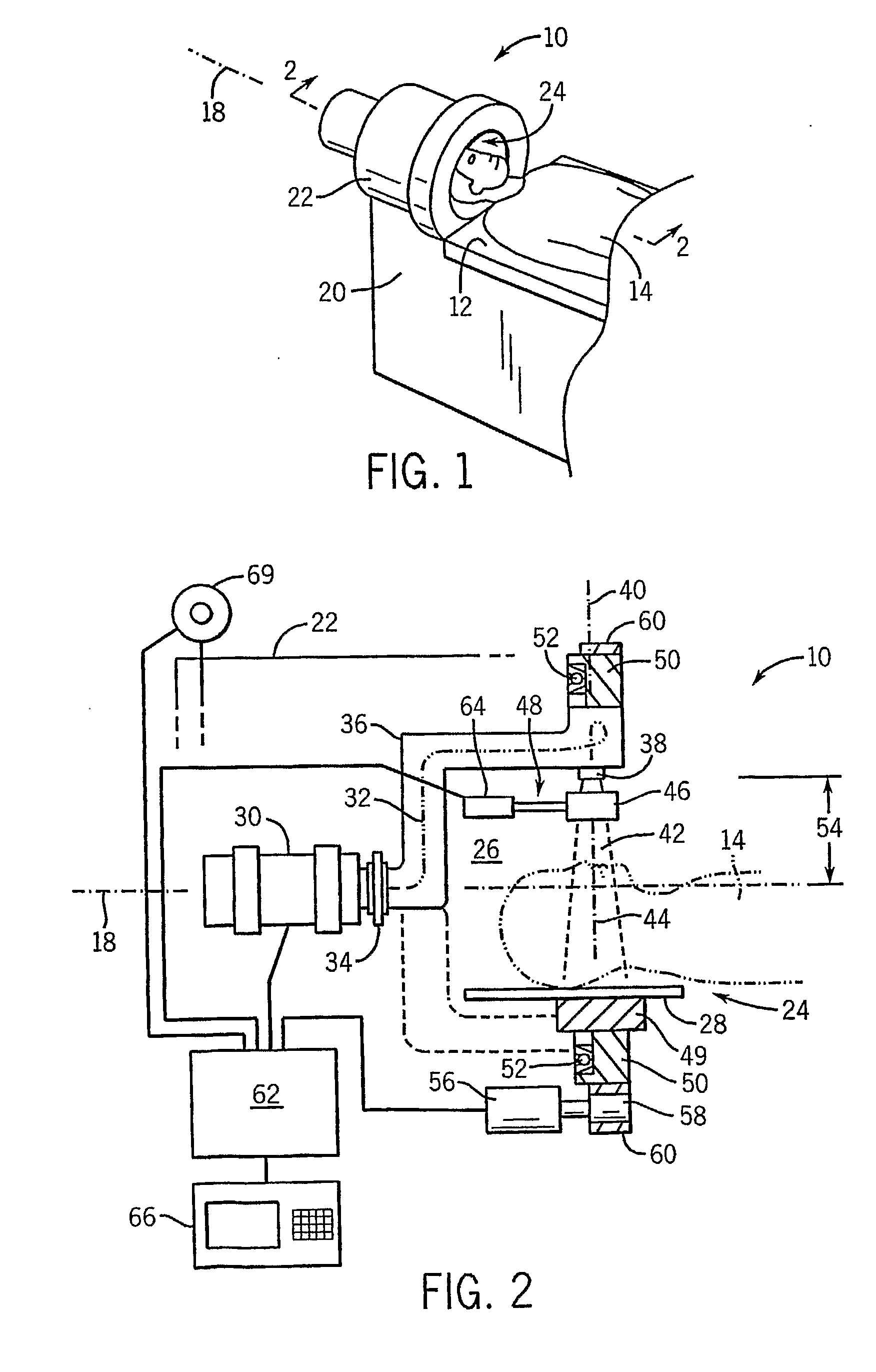
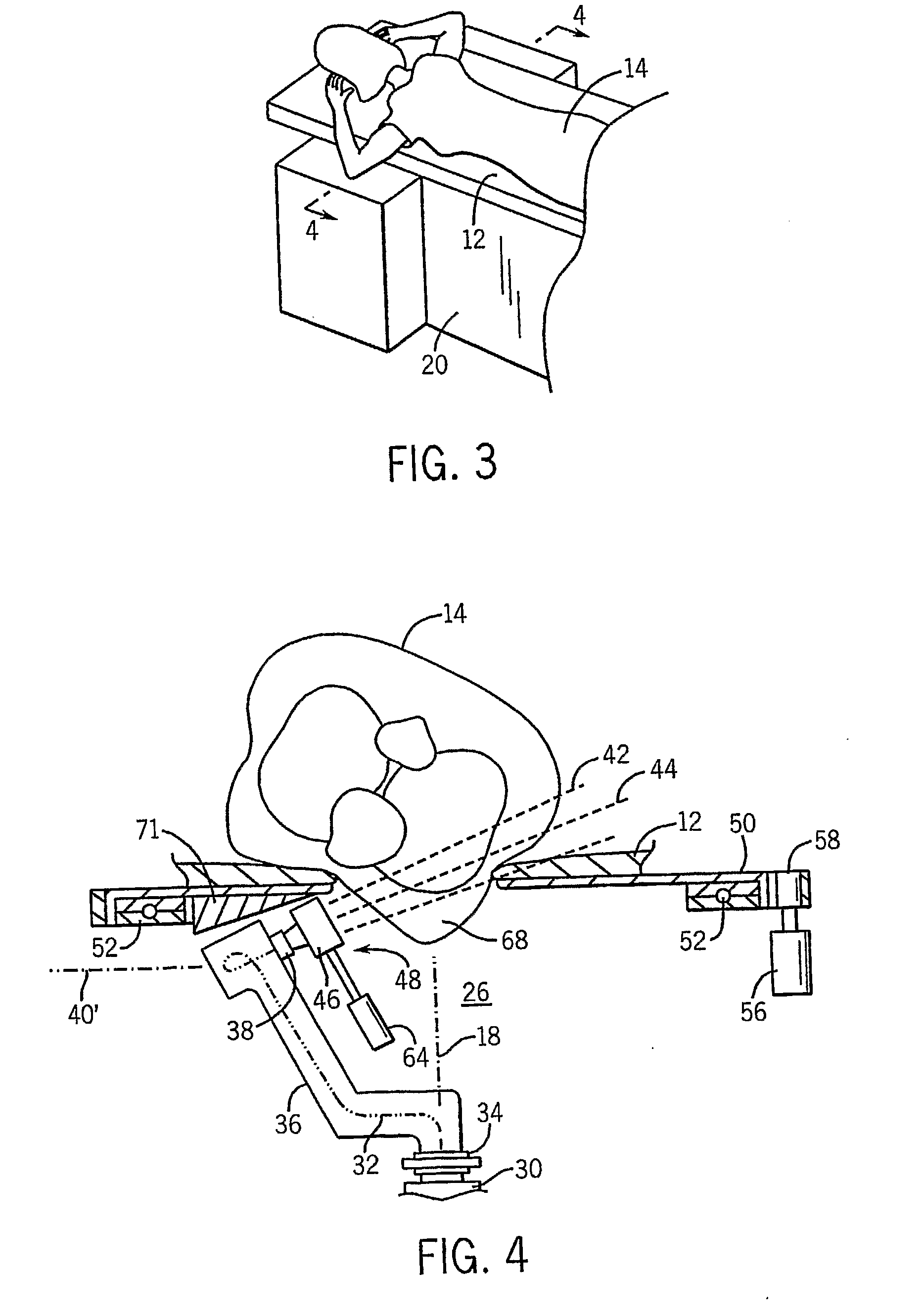
[0043] Referring now to FIG. 1, a first embodiment of the small field radiation therapy device 10 provides a patient table 12 for supporting a patient 14 along a longitudinal rotation axis 18.

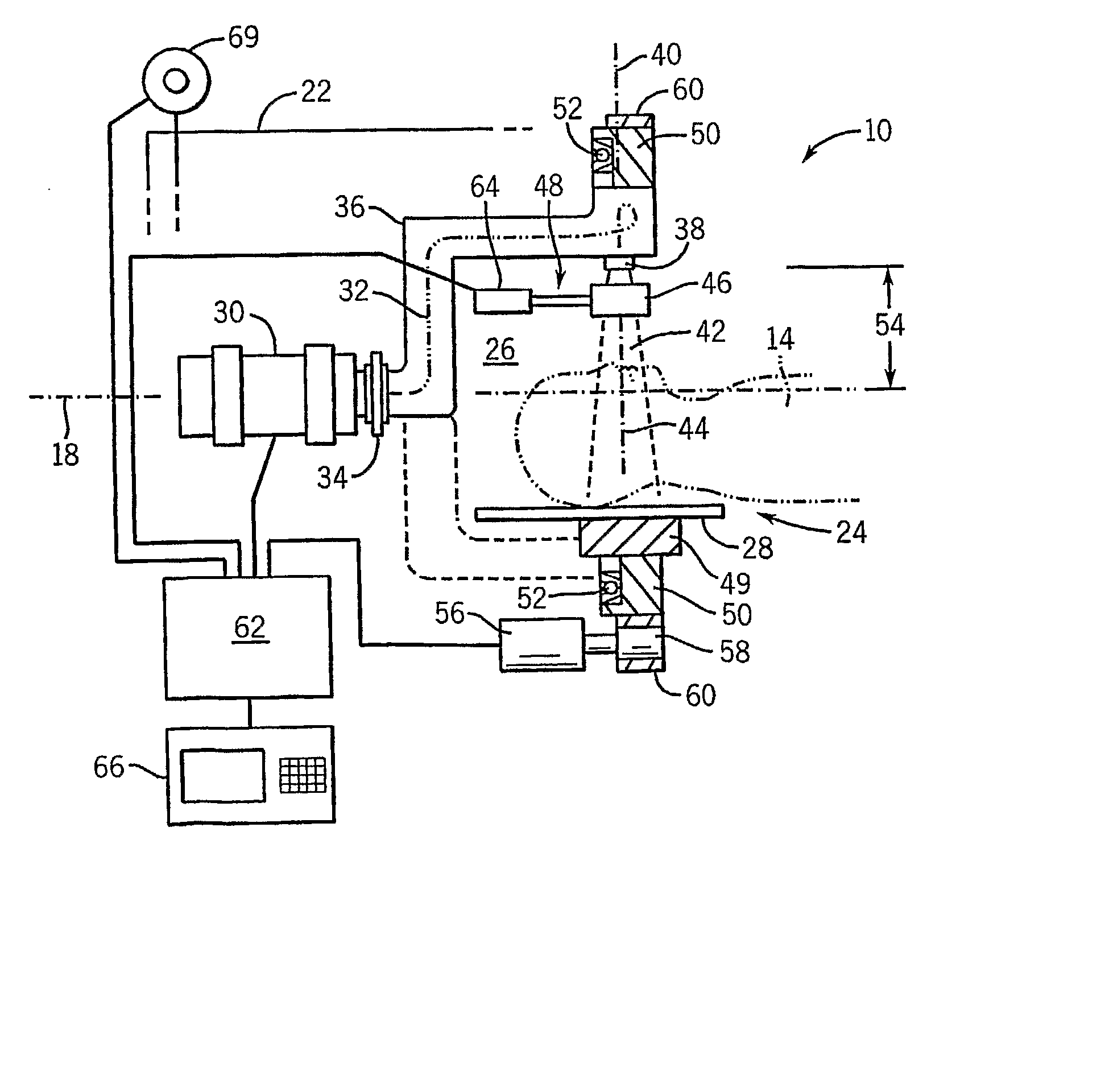
[0044] Referring also to FIG. 2, the table 12 is supported on a base 20 that also holds a gantry housing 22 at one end of the table 12. The gantry housing 22 provides an opening 24 sized to receive the patient's head into a cavity 26 along the longitudinal axis. The cavity 26 provides a head support 28 employing radiolucent restraining cushions immobilizing the patient's head against rotation and unwanted movement during treatment.

[0045] A stationary linear accelerator 30 is positioned at a superior end of the gantry housing 22 to direct the stream of electrons 32 along the rotation axis 18 toward the patient 14. The electrons 32 are received by a rotating coupling 34 which connects the stationary linear accelerator 30 to a wave-guide 36. The wave-guide 36 extends initially along the rotation...


PUM


Abstract

A small field radiation therapy machine having an aperture diameter of 30 cm or less provides improved ray definition for specialized treatment of portions of the human body such as head a breast.

Description

CROSS-REFERENCE TO RELATED APPLICATIONS [0001] This application is based on provisional application 60 / 667,480 filed Apr. 1, 2005 and entitled “Limited Field Tomotherapy Machine” and claims the benefit thereof.STATEMENT REGARDING FEDERALLY SPONSORED RESEARCH OR DEVELOPMENT [0002] This invention was made with United States government support awarded by the following agency: NIH CA 088960. The United States has certain rights in this invention.BACKGROUND OF THE INVENTION [0003] The present invention relates to radiation therapy machines for treatment of tumors and the like and in particular to an intensity modulated radiation (IMRT) therapy machine for specialized treatment of portions of the body. [0004] In external beam radiation therapy, high-energy radiation is directed through a patient to the site of a tumor. Multiple beams intersecting at site of a tumor may be used to reduce the dose to the skin and other intervening tissue. The individual beams may be collimated to the outlin...

Claims


Application Information

Patent Timeline
Patent Type & Authority Applications(United States)
IPC IPC(8): A61N5/10
CPCA61N5/1042
Inventor MACKIE, THOMAS R.BECKER, STEWART J.JERAJ, ROBERT
Owner WISCONSIN ALUMNI RES FOUND
Why Eureka
Try Eureka