Bearing mechanism and spindle motor having the same

a bearing mechanism and spindle technology, applied in the direction of bearing components, mechanical equipment, shafts and bearings, etc., can solve the problems of shortening the operating life of the conventional bearing mechanism 122, shortening etc., to reduce the scattering, degradation and evaporation of oil, and prolong the operating life of the motor. , the effect of high oil viscosity

Inactive Publication Date: 2007-10-18
NIDEC CORP
View PDF8 Cites 13 Cited by
  • Summary
  • Abstract
  • Description
  • Claims
  • Application Information

AI Technical Summary

Benefits of technology

[0016] According to the preferred embodiment of the present invention, a rate of rotation of the spindle motor is increased and a value of electric current is decreased. Also, according to the preferred embodiment of the present invention, a factor shortening an operating life of the motor will be minimized.
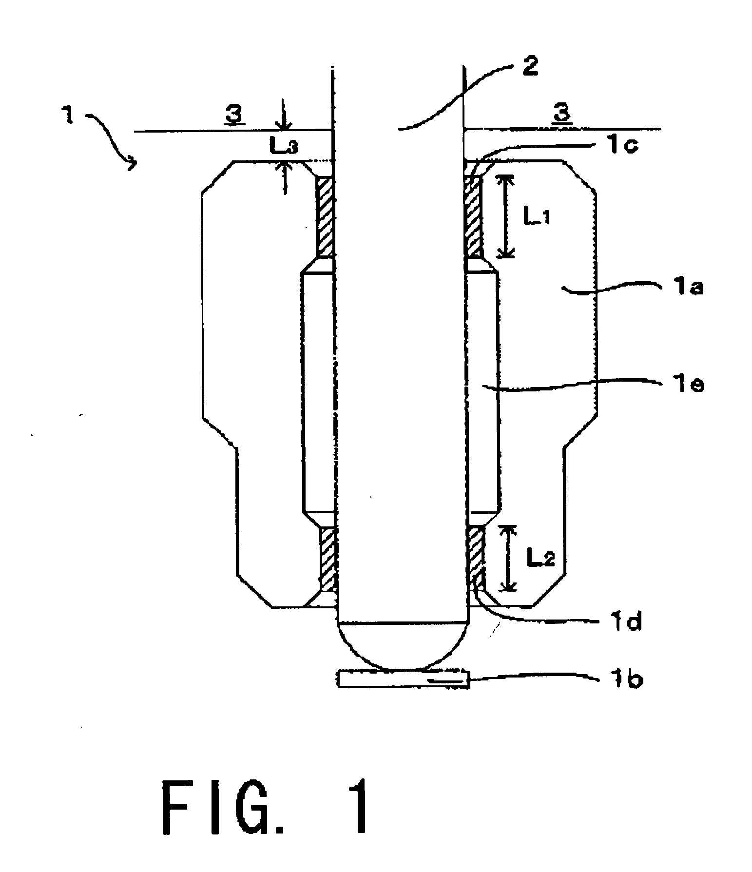
[0024] Also, due to the high viscosity of the oil used therein, the shaft makes contact with the bearing surfaces via the oil film, and therefore, the area at which the boundary lubrication is conducted will be reduced and the operating life of the motor will be extended.

Problems solved by technology

However, the conventional bearing mechanism 122 has following problems.
Also, the oil may be scattered due to centrifugal force generated by the rotor 110, thereby shortening the operating life of motor.

Method used


Image

  • Bearing mechanism and spindle motor having the same
  • Bearing mechanism and spindle motor having the same
  • Bearing mechanism and spindle motor having the same

Examples


Embodiment Construction

[0040] Hereinafter, a preferred embodiment of the present invention will be described with reference to FIGS. 1 to 7.

[0041] Note that in the description of the preferred embodiment of the present invention herein, words such as upper, lower, left, right, upward, downward, top, bottom for explaining positional relations between respective members and directions merely indicate positional relationships and directions in the drawings. Such words do not indicate positional relationships and directions of the members mounted in an actual device.

[0042] Also note that reference numerals, figure numbers and supplementary explanations are shown below for assisting the reader in finding corresponding components in the description of preferred embodiments below to facilitate the understanding of the present invention. It is understood that these expressions in no way restrict the scope of the present invention.

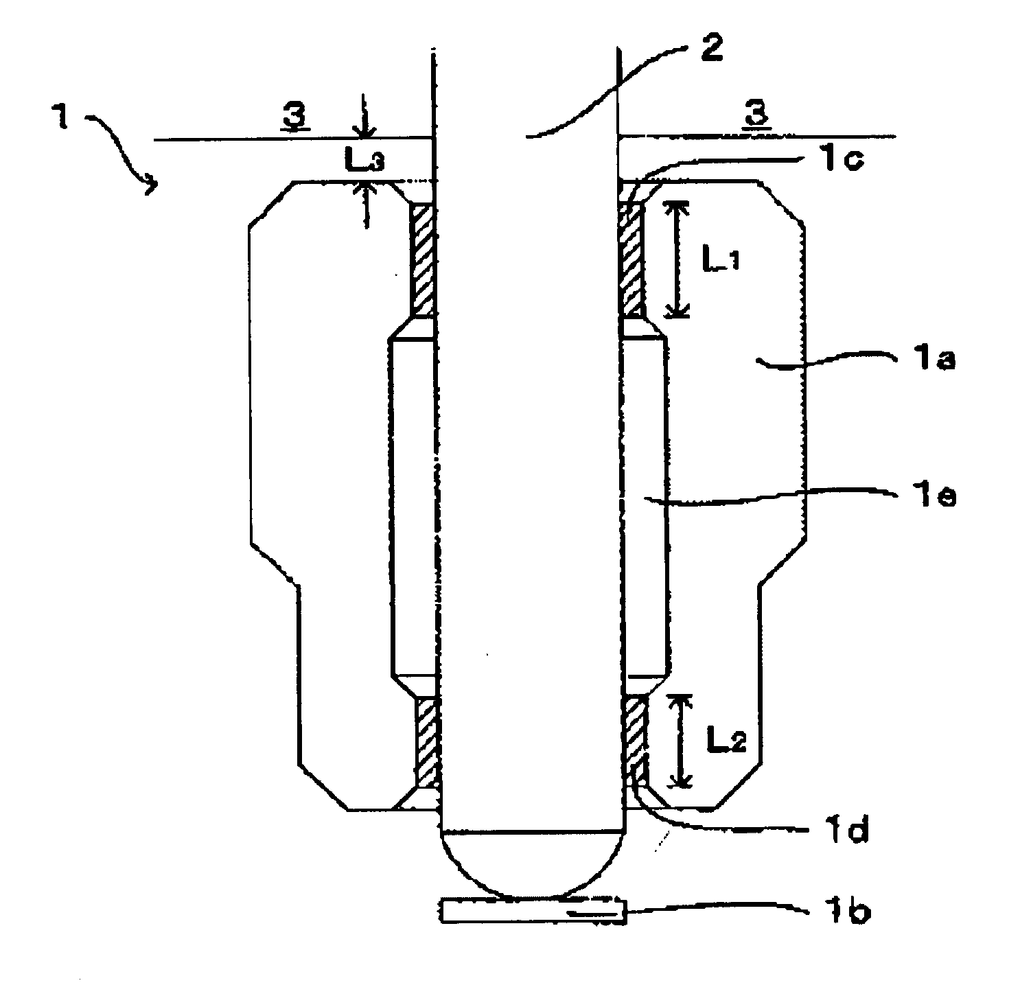
[0043]FIG. 1 is a diagram showing a cross sectional view of a bearing mechanism. ...


PUM


Abstract

A bearing mechanism having a sleeve including at an inner circumferential surface thereof a first bearing surface and a relief portion including a diameter greater than that of the first bearing surface is used in a spindle motor. An axial length of the first bearing surface is between approximately 1.2 mm and 1.8 mm. By virtue of such configuration, characteristics of the spindle motor are improved and an operating life of the spindle motor is extended.

Description

BACKGROUND OF THE INVENTION [0001] 1. Field of the Invention [0002] The present invention relates to a bearing mechanism and a spindle motor having the bearing mechanism for use in order to improve the characteristics of the spindle motor used in a disk driving device. [0003] 2. Description of the Related Art [0004] Conventionally, a spindle motor is used in a disk driving device in order to rotate a storage medium (e.g., DVD and / or CD). As shown in FIG. 8A, a spindle motor 100 comprises a rotor 110 and a stator 120. [0005] The rotor 110 includes a rotor case 111, a shaft 112 arranged at a central portion of the rotor case 111, and a rotor magnet 113 arranged at an outer circumferential portion of the rotor case 111. The stator 120 includes a stator core 121 arranged opposing to the rotor magnet 113, a bearing mechanism 122 for rotatably supporting the shaft 112, a bearing holder 123 for retaining the bearing mechanism 122, and a base plate 124 for fixing the bearing holder 123. [00...

Claims


Application Information

Patent Timeline
Patent Type & Authority Applications(United States)
IPC IPC(8): F16C33/02
CPCF16C33/107
Inventor NAKAGAWA, HISAYATAKIZAWA, MICHIAKINAKANISHI, TORUKANEKO, TAKESHI
Owner NIDEC CORP
Why Eureka
Try Eureka