

A method of catalyzing a reaction to form a urethane coating and a complex for use in the method
- Summary
- Abstract
- Description
- Claims
- Application Information
AI Technical Summary
Benefits of technology
Problems solved by technology
Method used
Image

Examples
examples
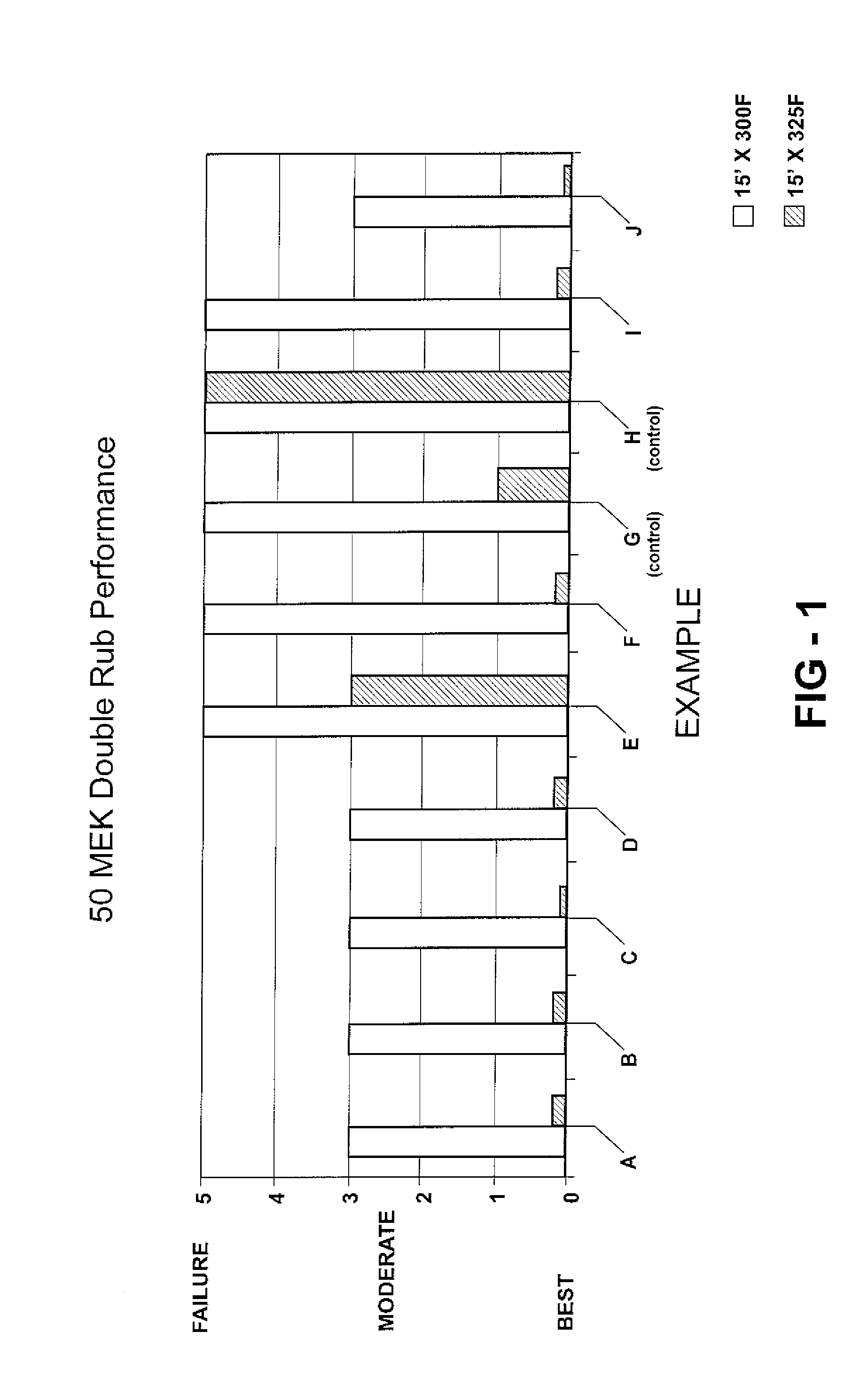
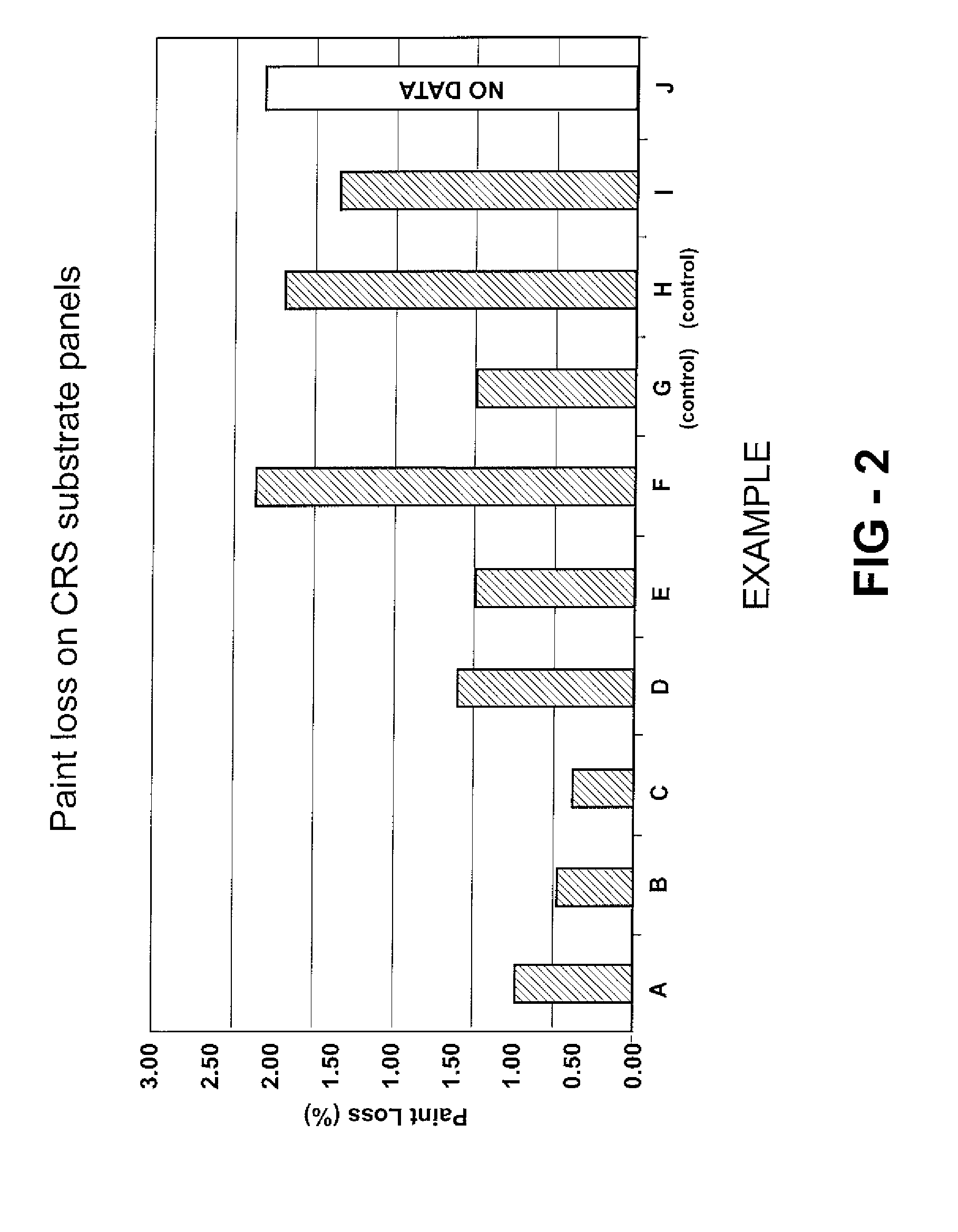
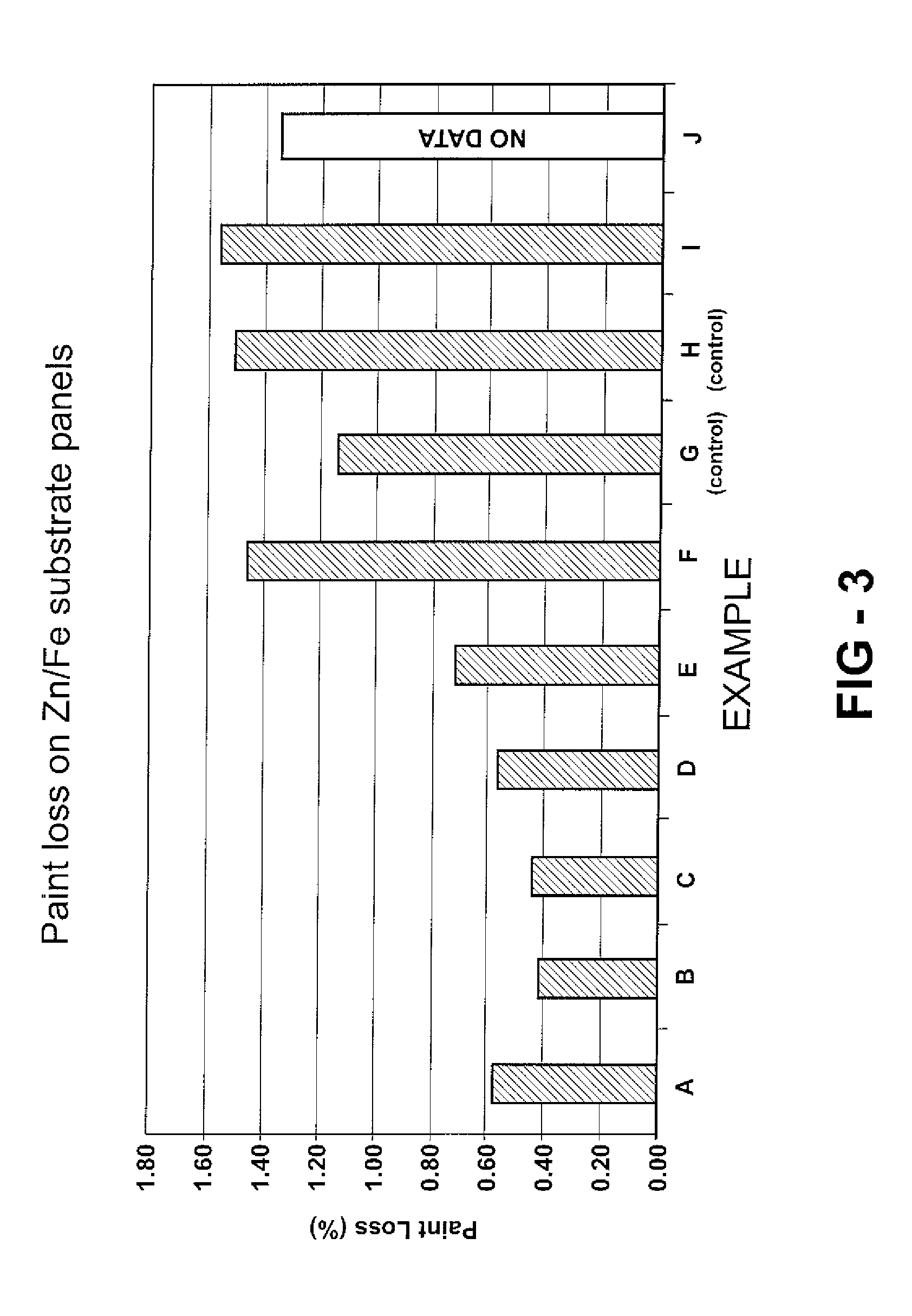
[0050] Twenty examples, specifically Examples A-T, are prepared as described below and as indicated in Tables 1A, 1B, 2A, and 2B. Examples A-T utilize Emulsion 1 and Examples K-T utilize Emulsion 2. Examples A-F, I, J-P, S, and T are examples according to the invention. Examples G and Q are one form of a control example where, although DDSA is included in the urethane coating composition, no metal catalyst is included Example H and R are another form of a control example where, although a metal catalyst is included in the urethane coating composition, no anhydride is included to carboxylate the resin. The examples are all urethane coating compositions, specifically urethane cationic electrodeposition coatings.
[0051] In these Examples, the hydroxy-functional resin is carboxylated with the anhydride, specifically with dodecenylsuccinic anhydride (DDSA). A suitable hydroxy-functional resin for these Examples is a cathodic electrodepositing resin. The DDSA is obtained from Dixie Chemic...
examples a-j
[0066]
TABLE 1AUrethaneCoatingRelativeCompositionLevel ofAmount of DDSAPigmentExampleEmulsionAnhydrideWt.mmolTaste4(Electrocoat Bath)1Type(DDSA)(%)2(%)3DBTOA1HIGH310DBTOB1HIGH310DBTOC1HIGH310DBTOD1HIGH310DBTOE1HIGH310DBTOF1HIGH310DBTOG1HIGH310DBTOH1———DBTOI1LOW 1.5 5DBTO J81HIGH310DBTO
[0067]
TABLE 1BUrethaneMetalCoatingOf MetalCompositionCatalyst inOxidationAmountExamplePigmentOfWt.mmol(Electrocoat Bath)Paste5Metal(%)6(%)7ATinIV0.54BBismuthIII0.52CZirconiumIV0.55DZincII0.58ECopperI0.58FYttriumIV0.56G————HZincII0.58IZincII0.58 J8ZincII0.58
Examples K-T
[0068]
TABLE 2AUrethaneCoatingRelativeCompositionLevel ofAmount of DDSAPigmentExampleEmulsionAnhydrideWt.mmolPaste4(Electrocoat Bath)1Type(DDSA)(%)2(%)3DBTOK2HIGH310DBTOL2HIGH310DBTOM2HIGH310DBTON2HIGH310DBTOO2HIGH310DBTOP2HIGH310DBTOQ2HIGH310DBTOR2———DBTOS2LOW 1.5 5DBTO T82HIGH310DBTO
[0069]
TABLE 2BUrethaneMetalCoatingOf MetalCompositionCatalyst inOxidationAmountExamplePigmentOfWt.mmol(Electrocoat Bath)Paste5Metal(%)6(%)7KTinIV0,54LBismu...
PUM
| Property | Measurement | Unit |
|---|---|---|
| Mass | aaaaa | aaaaa |
| Mass | aaaaa | aaaaa |
| Fraction | aaaaa | aaaaa |
Abstract
Description
Claims
Application Information