Gas-condition predicting device and diffusion-condition predicting system

a technology of diffusion-condition prediction and prediction device, which is applied in the direction of instruments, data acquisition and logging, and using reradiation, can solve the problems of less practicability and difficult methods to employ in actual situations, and achieve the effect of reducing processing tim

Inactive Publication Date: 2007-10-18
MITSUBISHI HEAVY IND LTD
View PDF10 Cites 25 Cited by
  • Summary
  • Abstract
  • Description
  • Claims
  • Application Information

AI Technical Summary

Benefits of technology

[0018]An object of the present invention is to provide a gas-condition predicting device, a gas-condition predicting method, a gas-condition predicting program, and a diffusion-condition predicting system in which the processing time can be decreased.

Problems solved by technology

However, since the above method of calculating air-flow parameters requires a considerably long calculation time, the method is difficult to employ in actual situations and is less feasible.

Method used


Image

  • Gas-condition predicting device and diffusion-condition predicting system
  • Gas-condition predicting device and diffusion-condition predicting system
  • Gas-condition predicting device and diffusion-condition predicting system

Examples


first embodiment

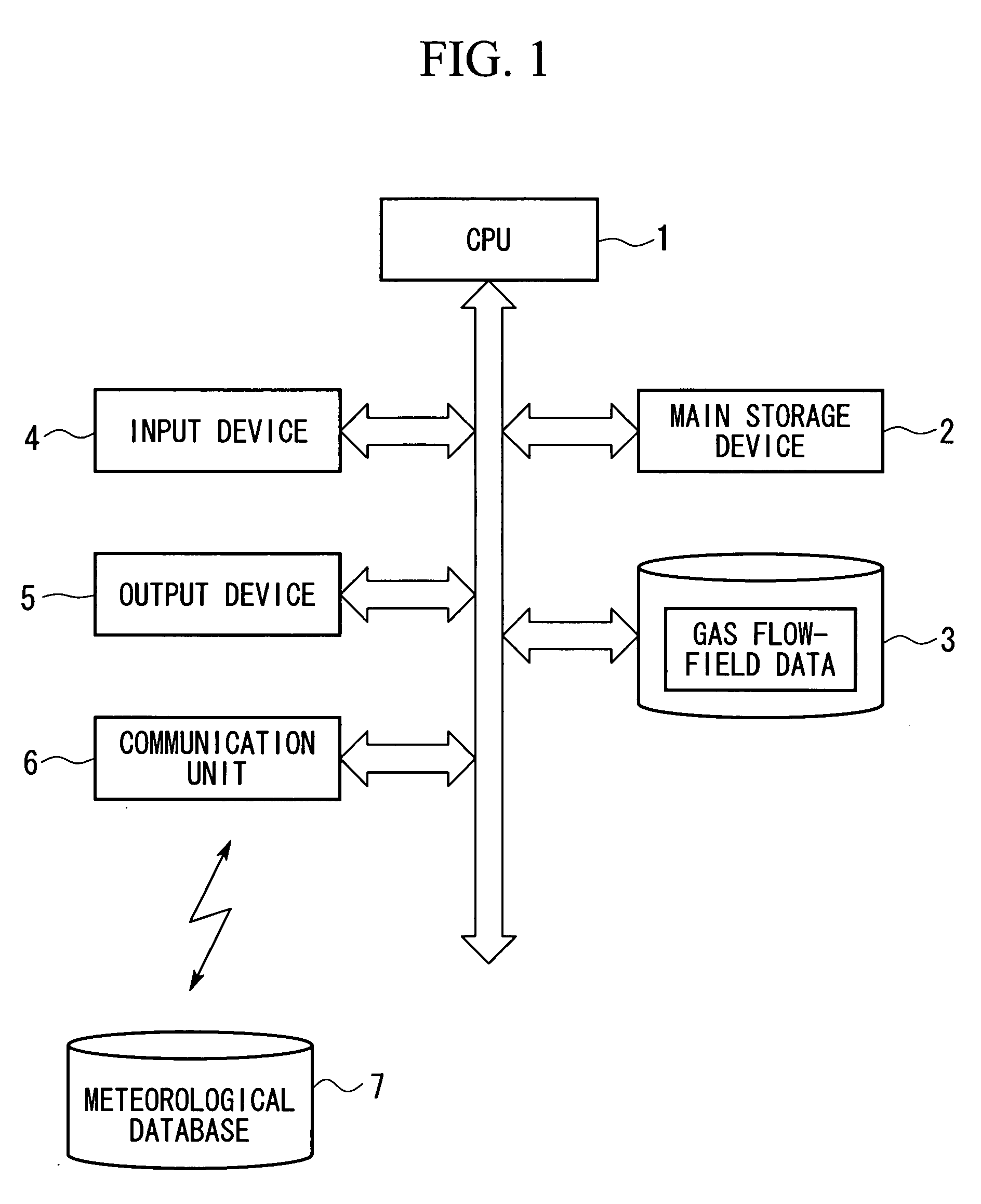
[0057]FIG. 1 is a block diagram showing the outline structure of a diffusion-condition predicting system according to a first embodiment of the present invention. The diffusion-condition predicting system of this embodiment predicts gas conditions in a target area, which is a predetermined area including a target point X at which a nuclear power plant or the like is located, and predicts diffusion conditions of a diffusate released from the target point X using the predicted gas conditions.

[0058]This diffusion-condition predicting system is a computer system including a central processing unit (CPU) 1, a main storage device 2 such as a random access memory (RAM), an auxiliary storage device (storage unit) 3 such as a read only memory (ROM) or a hard disk drive (HDD), an input device 4 such as a keyboard or a mouse, an output device 5 such as a display or a printer, a communication unit 6 that communicates with an external device, and the like.

[0059]In the auxiliary memory device 3, ...

second embodiment

[0097]A second embodiment of the present invention will now be described.

[0098]A diffusion-condition predicting system of this embodiment differs from the diffusion-condition predicting system of the above-described first embodiment in the function of the extraction unit 12.

[0099]Regarding the diffusion-condition predicting system of this embodiment, a description of the structure common to the first embodiment is omitted, and only structure different from the first embodiment will be described.

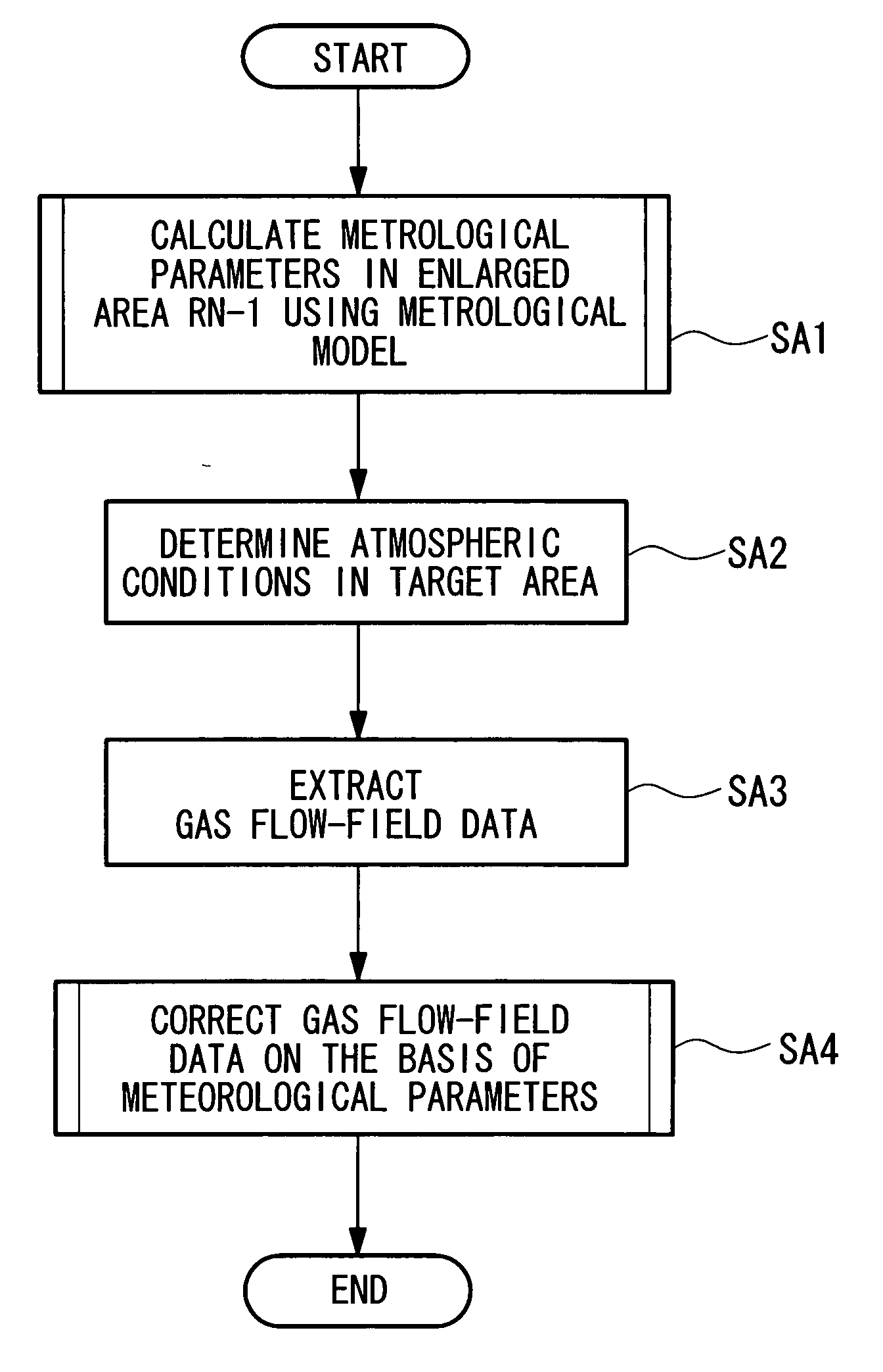
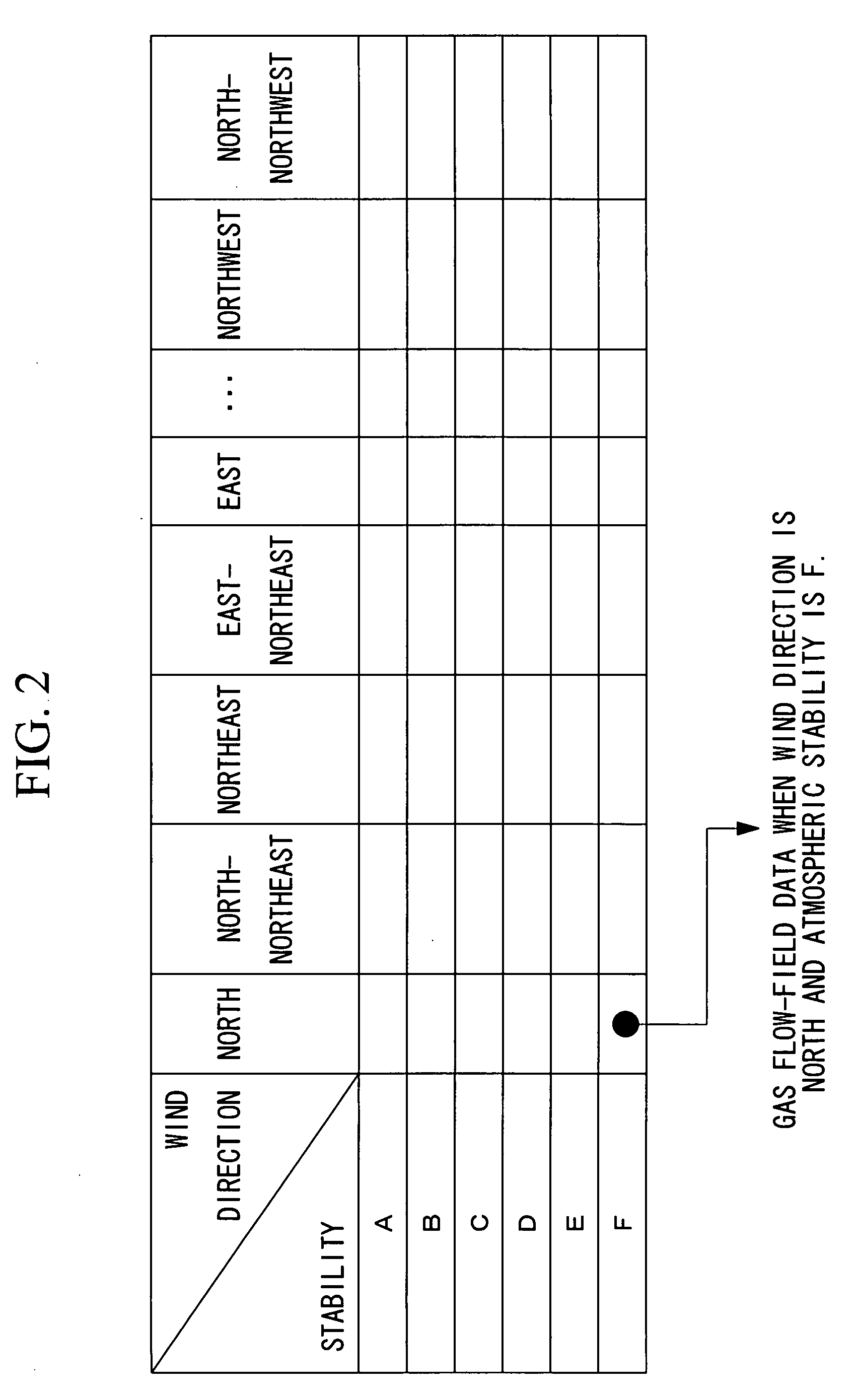
[0100]When the extraction unit 12 of this embodiment receives meteorological parameters at each evaluation point in the enlarged area RN-1 from the meteorological-modeling unit 11, the extraction unit 12 extracts atmospheric conditions relating to the boundary of the target area in the enlarged area RN-1 and calculates the averages of these meteorological parameters. For example, the extraction unit 12 selects meteorological parameters, such as wind direction, wind speed, and the amount of so...


PUM


Abstract

A gas-condition predicting device includes an auxiliary storage device for storing each atmospheric condition in association with gas flow-field data in a target area under the atmospheric condition; a meteorological-modeling unit for calculating, using a meteorological model calculation, meteorological parameters at a plurality of evaluation points defined in an enlarged area that includes the target area and that is larger than the target area; and an extraction unit for determining atmospheric conditions in the target area from the meteorological parameters calculated by the meteorological-modeling unit and extracting from the auxiliary memory device gas flow-field data corresponding to the atmospheric conditions.

Description

BACKGROUND OF THE INVENTION[0001]1. Field of the Invention[0002]The present invention relates to a gas-condition predicting device, a gas-condition predicting method, and a gas-condition predicting program for spatially and temporally determining dense gas conditions (such as wind direction and wind speed) from spatial and temporal approximate weather observation data, and to a diffusion-condition predicting system.[0003]This application is based on Japanese Patent Applications, Nos. 2006-112215 and 2006-254163, the contents of which are incorporated herein by reference.[0004]2. Description of Related Art[0005]Heretofore, diffusion-condition predicting systems have been known. When a radioactive material is released due to an accident from a facility treating nuclear materials, such diffusion-condition predicting systems predict the diffusion area and the diffusion concentration of the radioactive material to predict affected areas.[0006]In such a diffusion-condition predicting syst...

Claims


Application Information

Patent Timeline
Patent Type & Authority Applications(United States)
IPC IPC(8): G06F19/00G06F17/40G01W1/00G06Q10/04
CPCG01W1/10
Inventor HARA, TOMOHIROOHBA, RYOJIOKABAYASHI, KAZUKIYONEDA, JIROKOCHI, AKINORINUKATSUKA, SHIGEHIRO
Owner MITSUBISHI HEAVY IND LTD
Why Eureka
Try Eureka