Waste heat utilization device and control method thereof

a technology of waste heat recovery and control method, which is applied in the direction of mechanical equipment, machines/engines, transportation and packaging, etc., can solve the problem that therankine cycle may not function as a waste heat recovery system, and achieve the effect of improving the fuel consumption rate of the vehicle and reducing the cost of the fuel

Inactive Publication Date: 2007-10-25
DENSO CORP
View PDF6 Cites 52 Cited by
  • Summary
  • Abstract
  • Description
  • Claims
  • Application Information

AI Technical Summary

Benefits of technology

[0009]Because the control unit determines not only the waste fluid temperature but also the flowing state of the waste fluid, the Rankine cycle is ensured to be operated when the waste heat recovery is possible. As a result, the waste heat recovery can be performed effectively, and a fuel consumption rate of a vehicle can be improved.

Problems solved by technology

Therefore, the Rankine cycle may not function as a waste heat recovery system when the Rankine cycle is operated only based on the temperature of the engine-cooling water.

Method used


Image

  • Waste heat utilization device and control method thereof
  • Waste heat utilization device and control method thereof
  • Waste heat utilization device and control method thereof

Examples


first embodiment

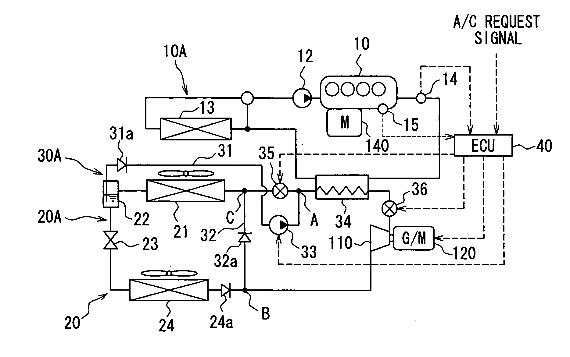
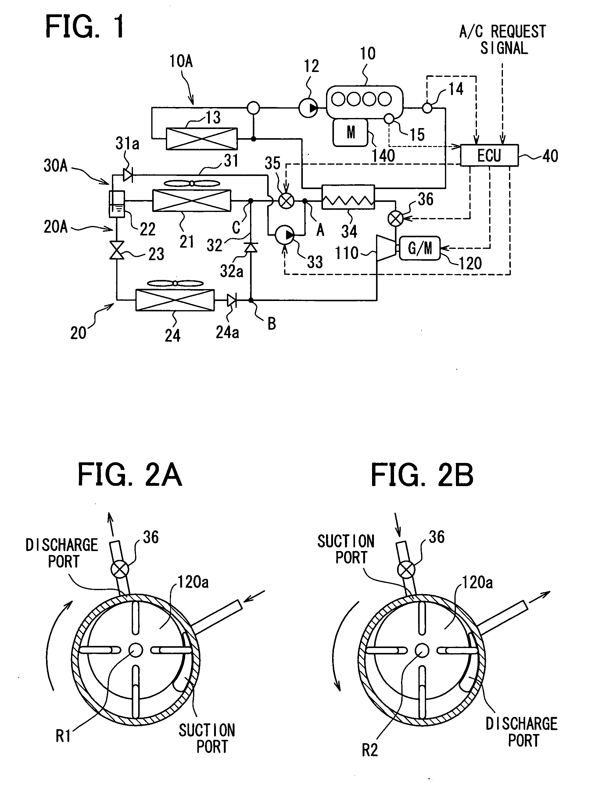
[0036]In a first embodiment, a waste heat utilization device 20 is typically used for a hybrid vehicle which has an electric motor 140 for driving, and an engine (heat engine) 10 being operated or stopped in accordance with a driving state of the vehicle. The waste heat utilization device 20 includes a refrigeration cycle 20A as a base cycle, and a Rankine cycle 30A for recovering an energy from a waste heat generated in the engine 10. At a compression part and expansion part of the cycles 20A and 30A, a compression / expansion unit 110 as a fluid machine is provided. The cycles 20A and 30 A, and the compression / expansion unit 110 are controlled by a control unit 40. The waste heat utilization device 20 according to the first embodiment will be described below with reference to FIG. 1.

[0037]The refrigeration cycle 20A moves heat from a low temperature side to a high temperature side for using a thermal energy for an air conditioning. The refrigeration cycle 20A includes the compressio...

second embodiment

[0068]A second embodiment of the invention will be described with reference to FIG. 10. In the first embodiment, the control unit 40 determines whether or not the flow amount of the engine-cooling water is sufficient amount, based on the signal of the rotation number of the engine 10. However, in the second embodiment, a flow amount sensor (flow amount detector) 41 is provided in the hot water circuit 10A for detecting the flow amount directly. A signal from the flow amount sensor 41 is input to the control unit 40. In the second embodiment, the water pump 12 may be the mechanical pump driven by the engine 10 similarly to the first embodiment, or may be an electric pump driven by an electric motor.

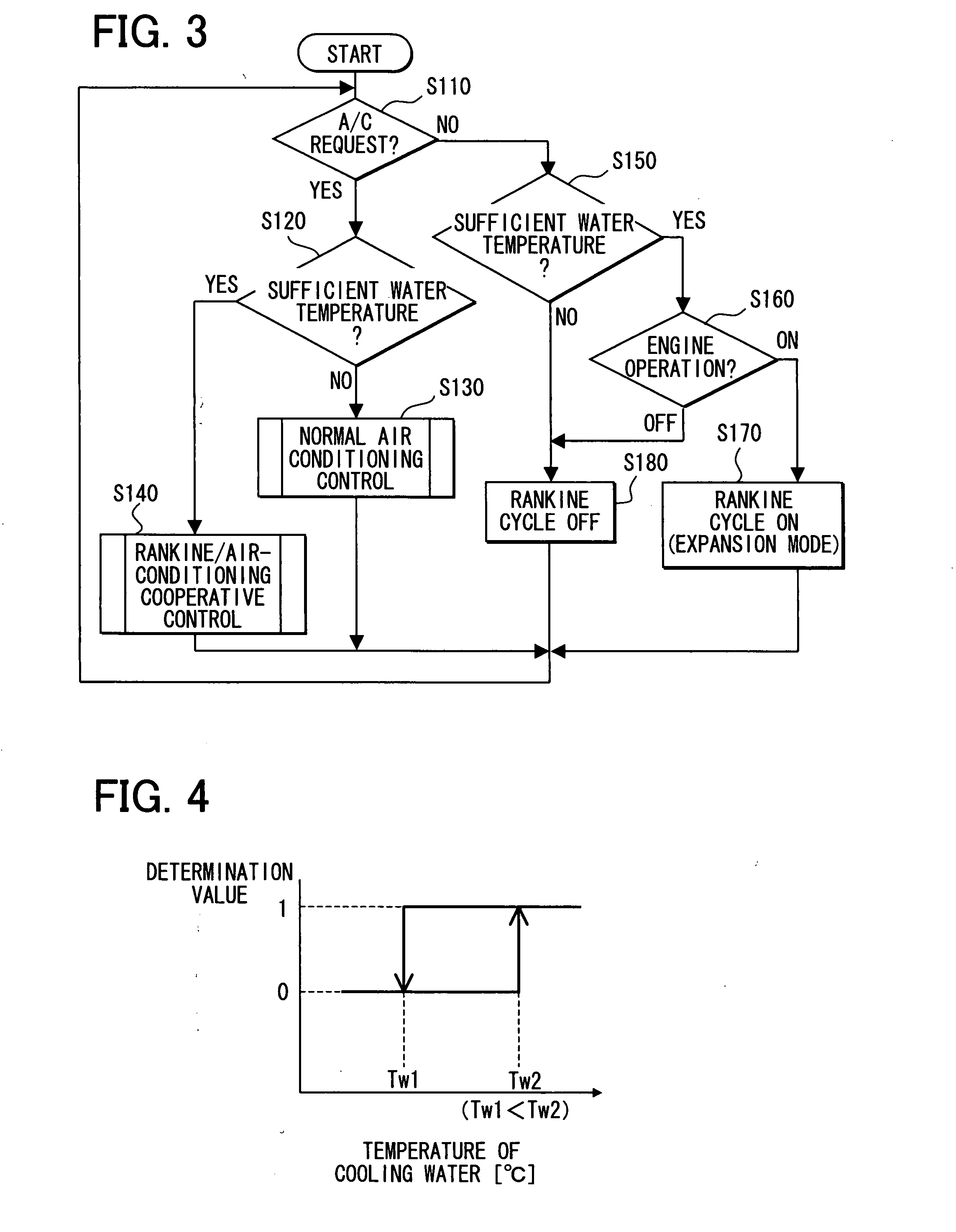
[0069]FIG. 11 is a flow diagram showing a control operation of the waste heat utilization device 20 by the control unit 40 according to the second embodiment. Steps S110 to 130, S150, S170, and S180 are same as those of the first embodiment.

[0070]In the first embodiment, it is determined w...

third embodiment

[0074]A third embodiment of the invention is described with reference to FIG. 14. In the first and second embodiments, the integral compression / expansion unit 110 formed by one fluid machine is used as the expander and the compressor. However, as shown in FIG. 14, it may use a compressor 130 and an expander 131 which are independent from each other, as the compression / expansion unit. The compressor 130 and the expander 131 are located in parallel with respect to a refrigerant flow, and switching valves 38a and 38b are provided in refrigerant passages connected to the compressor 130 and the expander 131. The waste heat utilizing device 20 may be controlled by the control unit 40 similarly to the first embodiment or the second embodiment. However, when the Rankine cycle 30A and the refrigeration cycle 20A are switched, the switching valves 38a and 38b are controlled by the control unit 40, as well as the liquid pump 33 and the switching valve 35.


PUM


Abstract

A waste heat utilization device includes a Rankine cycle in which an operation fluid circulates, and a control unit which controls an operation of the Rankine cycle. The Rankine cycle has a heater for heating the operation fluid using a waste fluid with a waste heat from a heat engine, an expander that expands the heated operation fluid to recover a mechanical energy, and a condenser for cooling and condensing the expanded operation fluid. The control unit operates the Rankine cycle when a waste fluid temperature is not less than a predetermined temperature and when the waste fluid is in a flowing state in the heat engine.

Description

CROSS REFERENCE TO RELATED APPLICATION[0001]This application is based on Japanese Patent Applications No. 2006-115924 filed on Apr. 19, 2006, and No. 2007-029566 filed on Feb. 8, 2007, the contents of which are incorporated herein by reference in its entirety.BACKGROUND OF THE INVENTION[0002]1. Field of the Invention[0003]The present invention relates to a waste heat utilization device and a control method thereof. For example, the waste heat utilization device can be used for recovering a waste heat of a vehicular engine.[0004]2. Description of the Related Art[0005]Conventionally, in a vehicle having a Rankine cycle, the Rankine cycle is operated only when a temperature (waste heat) of an engine-cooling water is not less than a predetermined temperature, and the Rankine cycle is stopped when the temperature is not sufficient, for example, as described in U.S. Pat. No. 6,928,820 (corresponding to JP-A-2005-155336). Therefore, an engine temperature can be prevented from decreasing ex...

Claims


Application Information

Patent Timeline
Patent Type & Authority Applications(United States)
IPC IPC(8): F01K23/06F01K25/06
CPCB60H1/00885B60H1/32B60H2001/00928F01K25/08F01K13/02F01K23/065B60H2001/00949
Inventor INABA, ATSUSHINISHIKAWA, MICHIOASA, HIRONORIUNO, KEIICHISUZUKI, TAKAHISAKISHITA, HIROSHI
Owner DENSO CORP
Why Eureka
Try Eureka