Exhaust heat recovery control device

a control device and heat recovery technology, applied in the direction of indirect heat exchangers, machines/engines, lighting and heating apparatus, etc., can solve the problems of condensed water produced in the exhaust heat recovery device damage to the catalyst unit for purifying exhaust gas, etc., to prevent or suppress freezing in the exhaust pipe, recover exhaust heat, reduce or limit the amount of heat recovered

Active Publication Date: 2016-10-04
TOYOTA JIDOSHA KK
View PDF15 Cites 0 Cited by
  • Summary
  • Abstract
  • Description
  • Claims
  • Application Information

AI Technical Summary

Benefits of technology

[0009]The invention causes recovery of exhaust heat and suppression of performance degradation due to the freezing of condensed water to be compatible with each other.
[0010]According to an aspect of the invention, there is provided an exhaust heat recovery control device including: a recovered heat adjusting unit configured to adjust an amount of heat recovered of exhaust gas by an exhaust heat recoverer recovering heat of exhaust gas; and a control unit configured to control the recovered heat adjusting unit so as to prevent or suppress freezing in an exhaust pipe based on a traveling history of a vehicle on which the exhaust heat recovery control device is mounted when the freezing in the exhaust pipe is predicted.
[0012]The control unit controls the recovered heat adjusting unit so as to prevent or suppress freezing in the exhaust pipe based on the traveling history when the freezing in the exhaust pipe is predicted. For example, when it is determined based on the traveling history that the freezing is not released, the freezing in the exhaust pipe can be released by controlling the recovered heat adjusting unit so as to reduce or limit the amount of heat recovered of exhaust gas. On the other hand, when it is determined based on the traveling history that the freezing is released, it is possible to recover exhaust heat by controlling the exhaust heat recoverer so as to recover heat or controlling the recovered heat adjusting unit so as to increase the amount of heat recovered. Accordingly, it is possible to cause the recovery of exhaust heat and the suppression of performance degradation due to the freezing of condensed water.
[0013]For example, the control unit may control the recovered heat adjusting unit so as to decrease the amount of heat recovered of exhaust gas by the exhaust heat recoverer when a previous traveling time as the traveling history is equal to or shorter than a predetermined reference time. That is, it can be determined based on the previous traveling time whether the freezing in the exhaust pipe is released. Accordingly, when the previous traveling time is equal to or shorter than a predetermined reference time, there is a high possibility that the inside of the exhaust pipe is frozen and it is thus possible to release the freezing in the exhaust pipe by controlling the recovered heat adjusting unit so as to decrease the amount of heat recovered.
[0015]As described above, according to the invention, it is possible to cause recovery of exhaust heat and suppression of performance degradation due to freezing of condensed water to be compatible with each other.

Problems solved by technology

The condensed water may cause damage to a catalyst unit for purifying exhaust gas, a switching valve for switching a flow channel of exhaust gas to an exhaust heat recoverer, and the like.
However, in an environment below the freezing point, there is a possibility that condensed water produced in the exhaust heat recoverer will be frozen in the exhaust pipe.

Method used


Image

  • Exhaust heat recovery control device
  • Exhaust heat recovery control device
  • Exhaust heat recovery control device

Examples


Embodiment Construction

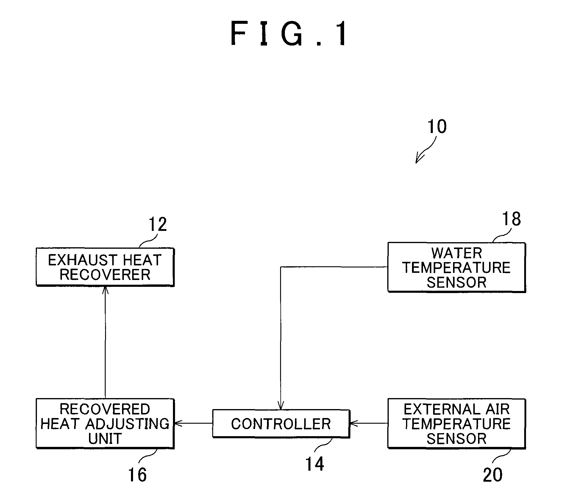
[0021]Hereinafter, an example of an embodiment of the invention will be described in detail with reference to the accompanying drawings. FIG. 1 is a block diagram schematically illustrating a configuration of an exhaust heat recovery control device according to an embodiment of the invention.

[0022]In an exhaust heat recovery control device 10, a recovered heat adjusting unit for adjusting an amount of heat recovered by an exhaust heat recoverer 12 recovering heat of exhaust gas is connected to a controller 14 as the control unit.

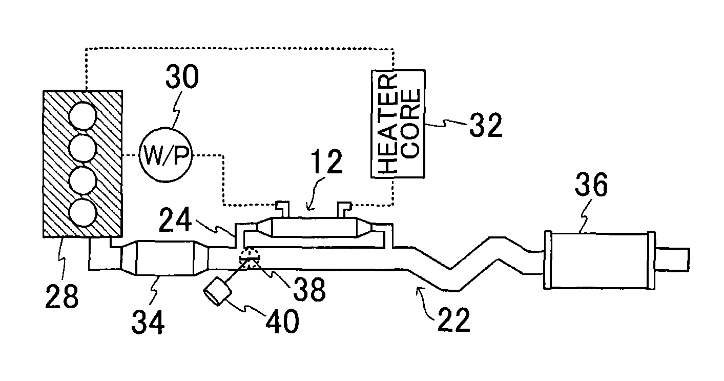
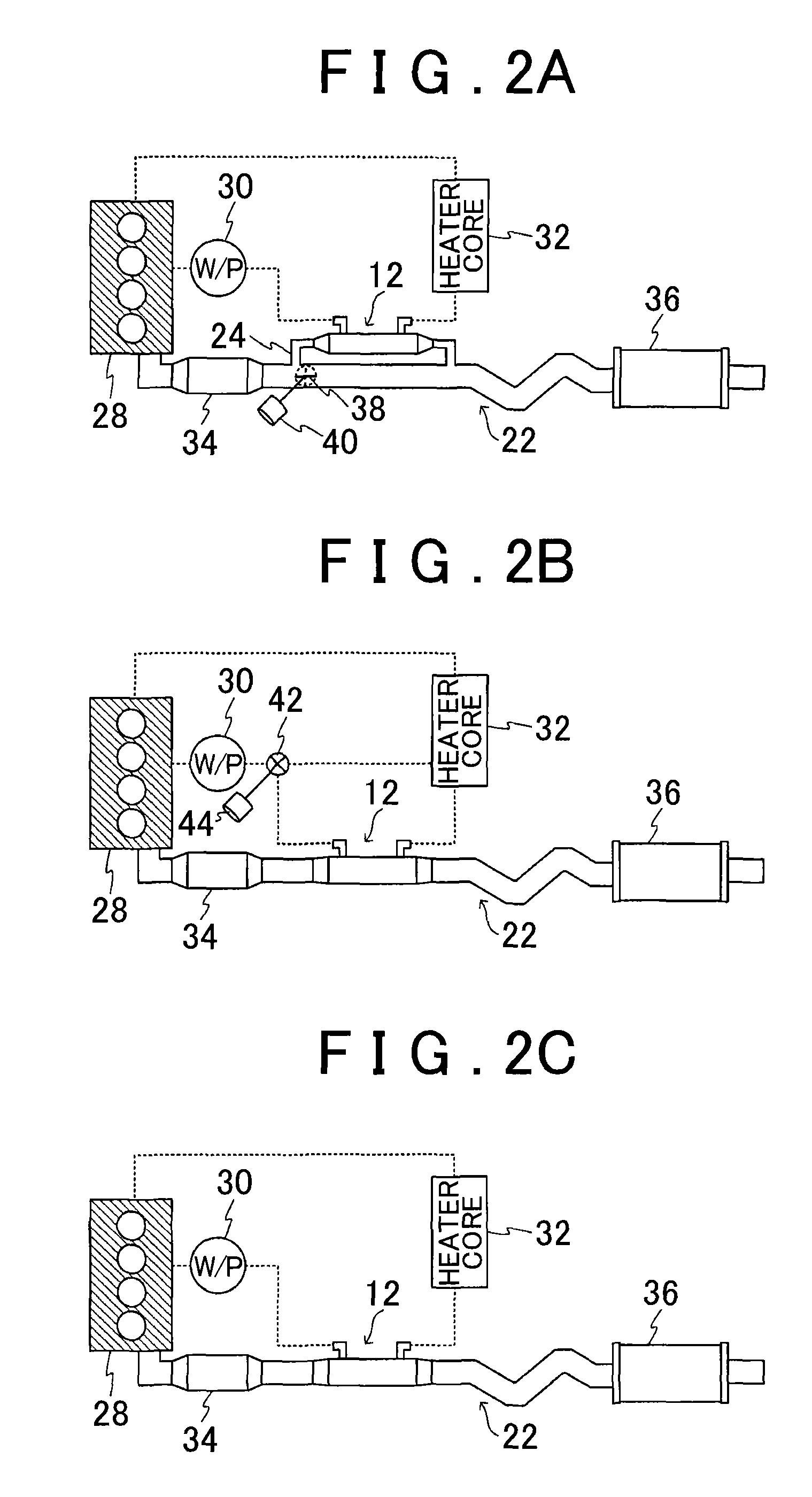
[0023]The exhaust heat recoverer 12 is disposed in an exhaust pipe through which exhaust gas of an automobile passes, recovers heat of the exhaust gas of the engine of the automobile, and uses the recovered heat for promotion of space heating or warming-up of an engine or the like.

[0024]The controller 14 controls the recovered heat adjusting unit so as to control whether to recover the heat of exhaust gas or an amount of heat recovered through the use of the...


PUM


Abstract

An exhaust heat recovery control device includes a recovered heat adjusting unit configured to adjust an amount of heat recovered of exhaust gas by an exhaust heat recoverer recovering heat of exhaust gas and a control unit configured to control the recovered heat adjusting unit so as to prevent or suppress freezing in an exhaust pipe based on a traveling history of a vehicle on which the exhaust heat recovery control device is mounted when the freezing in the exhaust pipe is predicted.

Description

INCORPORATION BY REFERENCE[0001]The disclosure of Japanese Patent Application No. 2014-019510 filed on Feb. 4, 2014 including the specification, drawings and abstract is incorporated herein by reference in its entirety.BACKGROUND OF THE INVENTION[0002]1. Field of the Invention[0003]The present invention relates to an exhaust heat recovery control device that controls an exhaust heat recoverer recovering exhaust heat of an exhaust pipe or the like.[0004]2. Description of Related Art[0005]In an exhaust heat recoverer recovering exhaust heat from an exhaust pipe or the like, condensed water may be produced by recovering exhaust heat and thus cooling exhaust gas. The condensed water may cause damage to a catalyst unit for purifying exhaust gas, a switching valve for switching a flow channel of exhaust gas to an exhaust heat recoverer, and the like.[0006]Therefore, Japanese Patent Application Publication No. 2006-161593 (JP 2006-161593 A) proposes an exhaust heat recovery system that pre...

Claims


Application Information

Patent Timeline
Patent Type & Authority Patents(United States)
IPC IPC(8): F01N5/02F01N9/00F02G5/02F01P7/14F01N3/02F28D21/00F01N3/00F01N3/04
CPCF01N5/02F01N9/00F01P7/14F02G5/02F01N3/005F01N3/0205F01N3/043F01N2240/02F01N2240/36F01N2260/024F01N2260/08F01N2900/0422F01N2900/08F01N2900/102F01P2025/13F01P2025/30F01P2060/08F01P2060/16F28D21/0003Y02T10/16Y02T10/166Y02T10/47Y02T10/12Y02T10/40F01N13/08F01P3/20
Inventor ISHIHATA, TAKATOHIRATA, YUICHIROMURATA, TOSHIOTAKAGAKI, NAKAYAKOMITSU, HIDEYUKIIRIYAMA, YOJIROWAKATSUKI, KAZUTOSHI
Owner TOYOTA JIDOSHA KK
Why Eureka
Try Eureka