Waste heat recovery power generation plant for sintering facility

a technology of sintering facility and waste heat recovery, which is applied in the direction of steam generation using hot heat carriers, machines/engines, lighting and heating apparatus, etc., can solve the problem of reducing gas flow, gas ducts and other problems, and the exhaust gas temperature condition required for sintering-machine waste heat boilers cannot be satisfied, so as to achieve the effect of improving the utilization rate of waste hea

Active Publication Date: 2017-01-24
KAWASAKI HEAVY IND LTD
View PDF13 Cites 0 Cited by
  • Summary
  • Abstract
  • Description
  • Claims
  • Application Information

AI Technical Summary

Benefits of technology

[0019]An object to be achieved by the present invention is to provide a waste heat recovery power generation plant for sintering facility, which can effectively recover a waste heat of a sintering machine, which could not be fully utilized in conventional cases, so as to improve a waste heat recovery rate of the sintering facility, by recovering a waste heat of a sintered-ore cooler while preventing that sulfuric anhydride contained in an exhaust gas of the sintering machine condenses into sulfuric acid drops.
[0022]According to the waste heat recovery power generation plant of the present invention, power can be generated by recovering a waste heat generated in a sintering machine, which could not be fully recovered conventionally, while preventing corrosion caused sulfuric acid contained in an exhaust gas of the sintering machine, whereby a waste heat utilization rate can be improved as a whole.

Problems solved by technology

When powdery iron ore is directly loaded into a shaft furnace, the shaft furnace is clogged by the powdery iron ore thus inhibiting the flow of a reduction gas.
Thus, there is a possibility that an outlet portion of the sintered-ore-cooler waste heat boiler, an exhaust gas treatment apparatus provided on a passage through which an exhaust gas of the sintering machine flows, a gas duct and so on might be corroded and damaged.
Thus, when the sintering machine and the waste heat boiler are combined based on the technical idea of the waste heat power generation system of the cement calcination plant disclosed in Patent Document 2, an exhaust gas temperature condition required for the sintering-machine waste heat boiler cannot be satisfied.
For example, the exhaust gas may be excessively cooled, causing the outlet portion of the sintered-ore-cooler waste heat boiler and an exhaust gas system to be damaged.
Thus, the technical idea of the waste heat power generation system of the cement calcination plant cannot be applied directly to the sintering facility.
Thus, a waste heat of an exhaust gas of the sintering machine cannot be effectively recovered in conventional cases.

Method used


Image

  • Waste heat recovery power generation plant for sintering facility
  • Waste heat recovery power generation plant for sintering facility
  • Waste heat recovery power generation plant for sintering facility

Examples


example 1

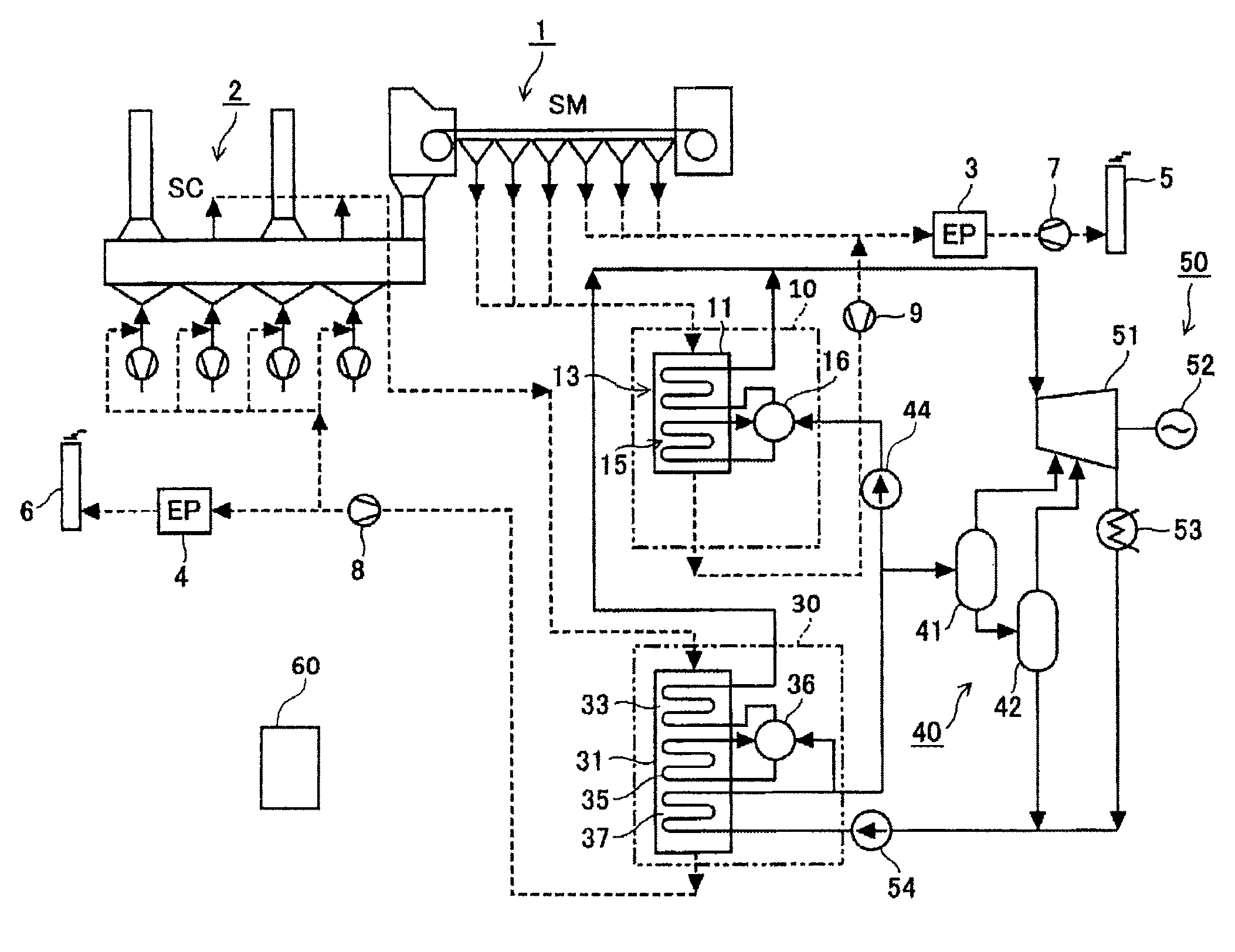
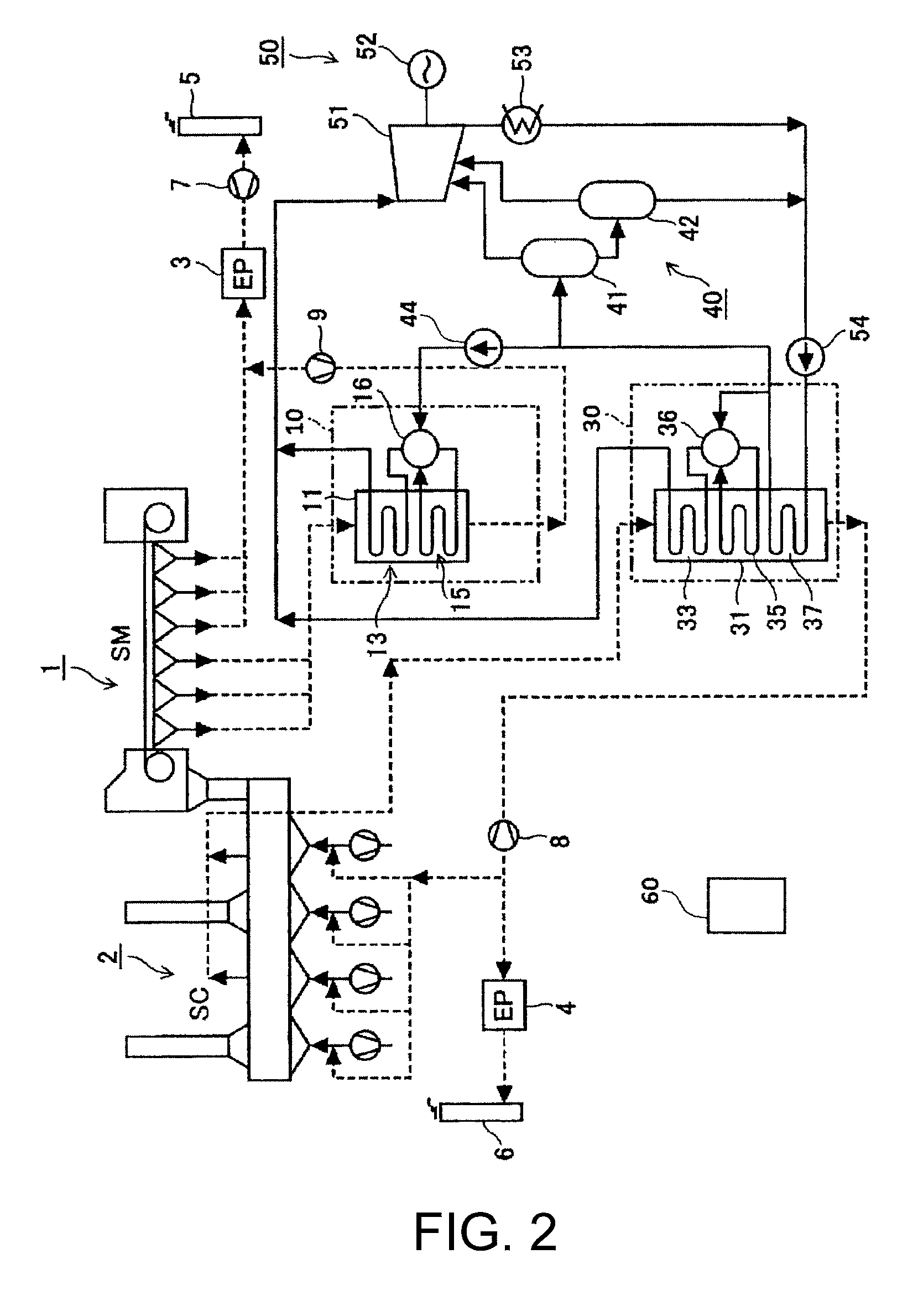
[0043]FIG. 2 is a block view of a waste heat recovery power generation plant for sintering facility according to a first example of the present invention.

[0044]The sintering machine 1, which is of a most general Dwight Lloyd type, obtains sintered ore by the following manner. A granulated sintering material, which was formed by mixing ore powder of a diameter of 2 mm to 3 mm, lime powder serving as a solvent and coke powder serving as a fuel, is put into an iron palette in a machine and is burned. While the sintering material in the palette is moved toward a terminal portion, an air flow generated by suction of an exhauster 7 is fed from above to below to burn the coke powder. The ore powder is partially melted by a combustion heat of the coke so as to be bonded, whereby sintered ore is obtained. The sintered ore is fragmented and selected, so that sintered ore pellets having a diameter of 15 mm to 30 mm are obtained. Then, the sintered ore is put into the sintered-ore cooler 2.

[004...

example 2

[0080]FIG. 4 is a block view of a waste heat recovery power generation plant for sintering facility according to a second example of the present invention. In FIG. 4, an element having the same function as that of FIG. 2 is shown by the same reference number as that of FIG. 2, and detailed description thereof is omitted for simplicity.

[0081]The waste heat recovery power generation plant in the second example differs from the waste heat recovery power generation plant in the first example in that the sintering-machine waste heat boiler (SM boiler) 10 is further provided with an economizer (second economizer) 17, and that a pipe system is changed a little. There is no other significant difference therebetween in other structure.

[0082]In the waste heat recovery power generation plant in this example, water supplied from a condenser 53 and a low-pressure stage flasher 42 by means of a feed pump 54 is heated by an economizer 37 of an SC boiler 30 into hot water, and the hot water is supp...


PUM

PropertyMeasurementUnit
temperatureaaaaaaaaaa

Abstract

To provide a waste heat recovery power generation plant for sintering facility capable of efficiently recovering a waste heat of a sintering machine in addition to that of a sintered-ore cooler, while restraining that sulfuric anhydride contained in an exhaust gas of the sintering machine forms drops. An SM boiler is configured to heat all of or a part of hot water generated by an SC boiler, by introducing a high temperature part of an exhaust gas of a sintering machine. At this time, a temperature of the hot water to be supplied to the SM boiler is controlled such that a temperature of an exhaust gas at an exhaust-gas temperature of the SM boiler is maintained at a temperature higher than an acid dew point.

Description

TECHNICAL FIELD[0001]The present invention relates to a waste heat recovery power generation plant to be applied to a sintering facility for generating sintered ore, which is composed of a sintering machine and a sintered-ore cooler.BACKGROUND ART[0002]Main iron ores used in steel plants are uniform powdery iron ore made by blending powdered iron ores of different origins / proveniences and different properties. When powdery iron ore is directly loaded into a shaft furnace, the shaft furnace is clogged by the powdery iron ore thus inhibiting the flow of a reduction gas. Therefore, in general, small amounts of lime powder and coke are mixed with powdery iron ore in advance, and the powdery iron ore thus mixed with the lime powder and the coke is sintered in a sintering machine into sintered ore pellets of a certain size. In Japan, sintered ores currently account for substantially 75% of the iron ores loaded into a shaft furnace.[0003]The sintered ore is manufactured according to the fo...

Claims


Application Information

Patent Timeline
Patent Type & Authority Patents(United States)
IPC IPC(8): F01K27/02F01K11/02F01K7/18C22B1/20F22B1/18F01N5/02
CPCF01K27/02C22B1/20F01K7/18F01K11/02F01N5/025F22B1/183Y02P80/15
Inventor KAMAZAWA, KAZUTOOHASHI, TOSHIKITAKIMOTO, TOMOJIYASUHARA, KATSUKI
Owner KAWASAKI HEAVY IND LTD
Why Eureka
Try Eureka