Fuel cell
a fuel cell and fuel technology, applied in the field of fuel cells, can solve the problems of easy drying in the downstream region of the fuel supply layer, and achieve the effect of reducing the non-uniformity of moisture and rapid increase of the power generation performance of the electrolyte membrane after activation
- Summary
- Abstract
- Description
- Claims
- Application Information
AI Technical Summary
Benefits of technology
Problems solved by technology
Method used
Image

Examples
embodiment 1
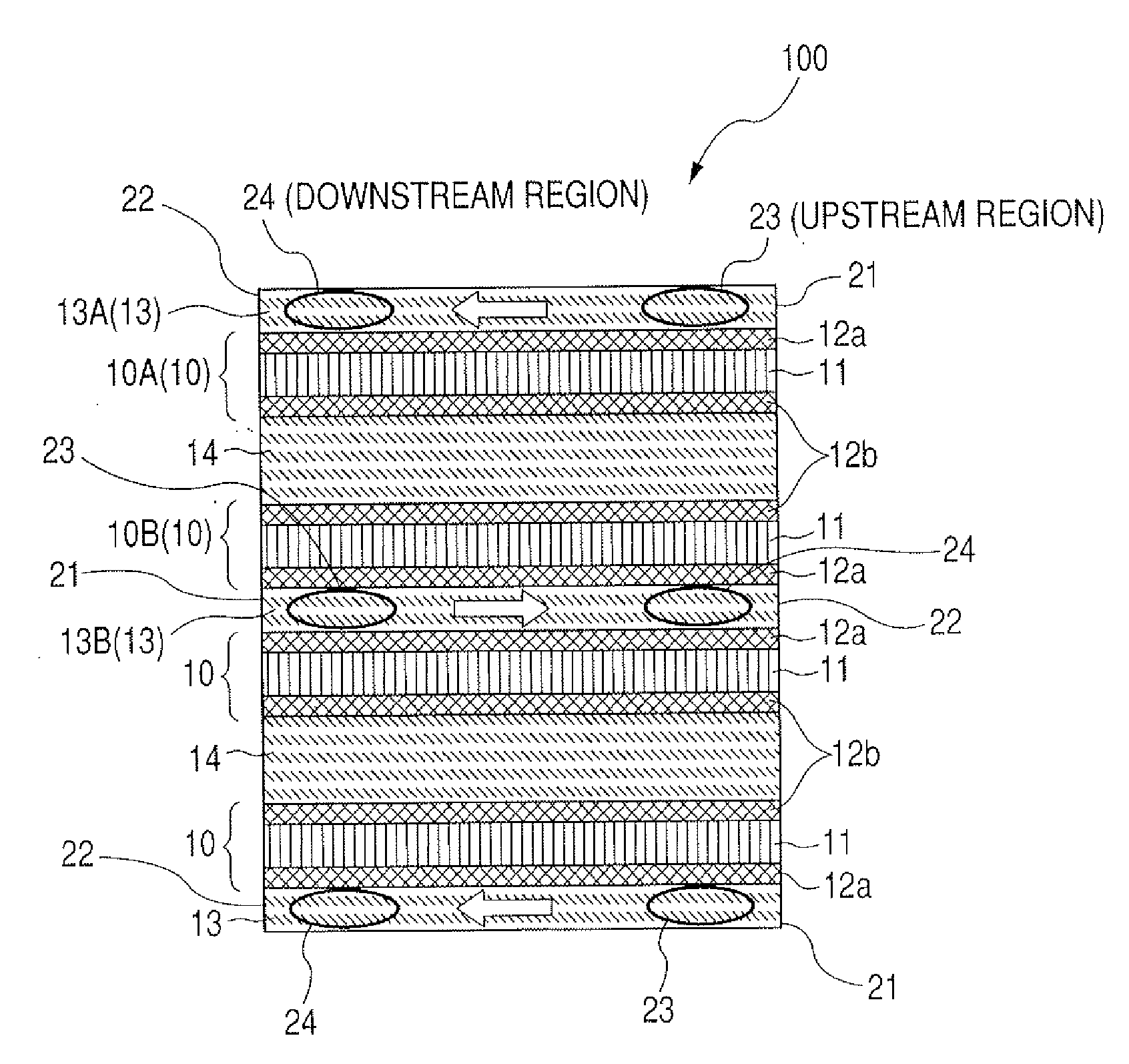
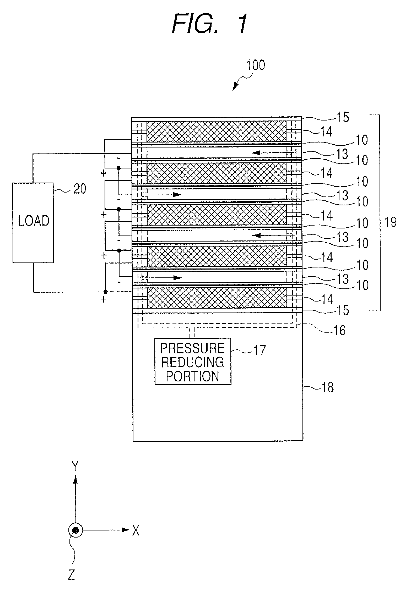
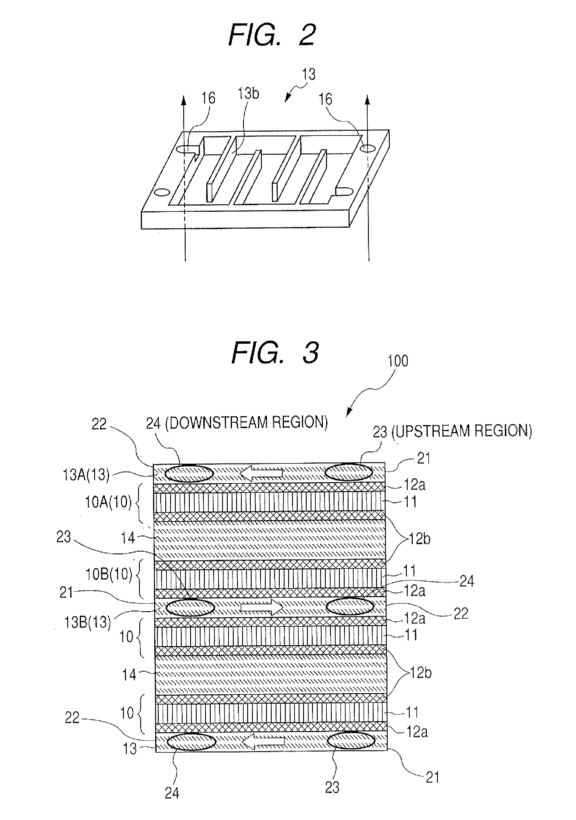
[0032]FIG. 1 is an explanatory diagram illustrating the configuration of a fuel cell according to Embodiment 1. FIG. 2 is a perspective view of appearance of a fuel supply layer. FIG. 3 is an explanatory diagram illustrating the flow of hydrogen gas in the fuel supply layer. FIG. 4 is an explanatory diagram illustrating the relationship between the flow of hydrogen gas and the movement of moisture.
[0033]As illustrated in FIG. 1, a fuel cell 100 of the first embodiment includes a fuel tank 18 for storing hydrogen gas and a power generation portion 19 which performs an electrochemical reaction of hydrogen gas stored in the fuel tank 18 to generate power. The power generation portion 19 has a structure in which an oxygen supply layer 14 and a fuel supply layer 13 are alternately stacked through a membrane electrode assembly 10 in the thickness direction (Y) of the fuel supply layer 13 and end plates 15 are disposed on both ends of the unit. The upper and lower surfaces of the stacked o...
embodiment 2
[0054]FIG. 5 is a schematic cross-sectional view illustrating the configuration of a fuel cell according to Embodiment 2. The fuel cell 200 of this second embodiment is partly different from that of Embodiment 1 in the supply line of hydrogen gas. Other than that, the fuel cell 200 is configured in the same way as that in Embodiment 1, so that the elements which are common to those in FIGS. 1 to 4 are identified like reference characters and detailed description thereof is omitted.
[0055]As illustrated in FIG. 5, in the fuel cell 200 of this second embodiment, the right-hand opening of a second fuel supply layer 13B in the figure is connected in series to the right-hand opening of a first fuel supply layer 13A in the figure using a supply line path 16B to communicate with each other. Further, the left-side opening of the second fuel supply layer 13B in the figure is taken to be an inlet 21 and the left-side opening of the first fuel supply layer 13A in the figure is taken to be an ou...
embodiment 3
[0057]Although the first and the second embodiments have a structure in which the oxygen supply layers 14 on and under which the membrane electrode assemblies 10 are disposed and the fuel supply layer 13 are stacked in a plurality of stages, the pair of fuel supply layers 13 sharing the oxygen supply layer 14 does not always need to have the membrane electrode assemblies 10 disposed thereon and thereunder. There may also be adopted such a configuration that an airtight material having a layer with gas permeability formed on one surface thereof is used and the surface of the layer with gas permeability is connected to the membrane electrode assembly 10.
[0058]As suggested in FIG. 4A, the fuel cell of this third embodiment has a three layer structure in which a pair of fuel supply layers sharing an oxygen supply layer is disposed. The membrane electrode assemblies are disposed between the oxygen supply layer and the fuel supply layers, respectively. The upper and lower surfaces and the...
PUM
 Abstract
Description
Claims
Application Information
 - R&D
- Intellectual Property
- Life Sciences
- Materials
- Tech Scout
- Unparalleled Data Quality
- Higher Quality Content
- 60% Fewer Hallucinations
Browse by: Latest US Patents, China's latest patents, Technical Efficacy Thesaurus, Application Domain, Technology Topic, Popular Technical Reports.
© 2025 PatSnap. All rights reserved.Legal|Privacy policy|Modern Slavery Act Transparency Statement|Sitemap|About US| Contact US: help@patsnap.com