Fuel cell system and fuel cell control method

a fuel cell and control method technology, applied in the direction of fuel cells, fuel cells, fuel cell grouping, etc., can solve the problems of not taking into account the conditions under which the power generation performance may be quickly recovered, and achieve the effect of quick recovery of the power generation performance of the cell

Inactive Publication Date: 2012-08-14
TOYOTA JIDOSHA KK
View PDF5 Cites 0 Cited by
  • Summary
  • Abstract
  • Description
  • Claims
  • Application Information

AI Technical Summary

Benefits of technology

[0010]The present invention provides a fuel cell system and a fuel cell control method that refrains from hydrating the electrolyte membrane of a fuel cell as long as conditions allow the power generation performance of the cell to be quickly recovered.

Problems solved by technology

However, the technique described in JP-A-2002-175821 does not take into account the conditions under which the power generation performance may be quickly recovered.

Method used


Image

  • Fuel cell system and fuel cell control method
  • Fuel cell system and fuel cell control method
  • Fuel cell system and fuel cell control method

Examples


Embodiment Construction

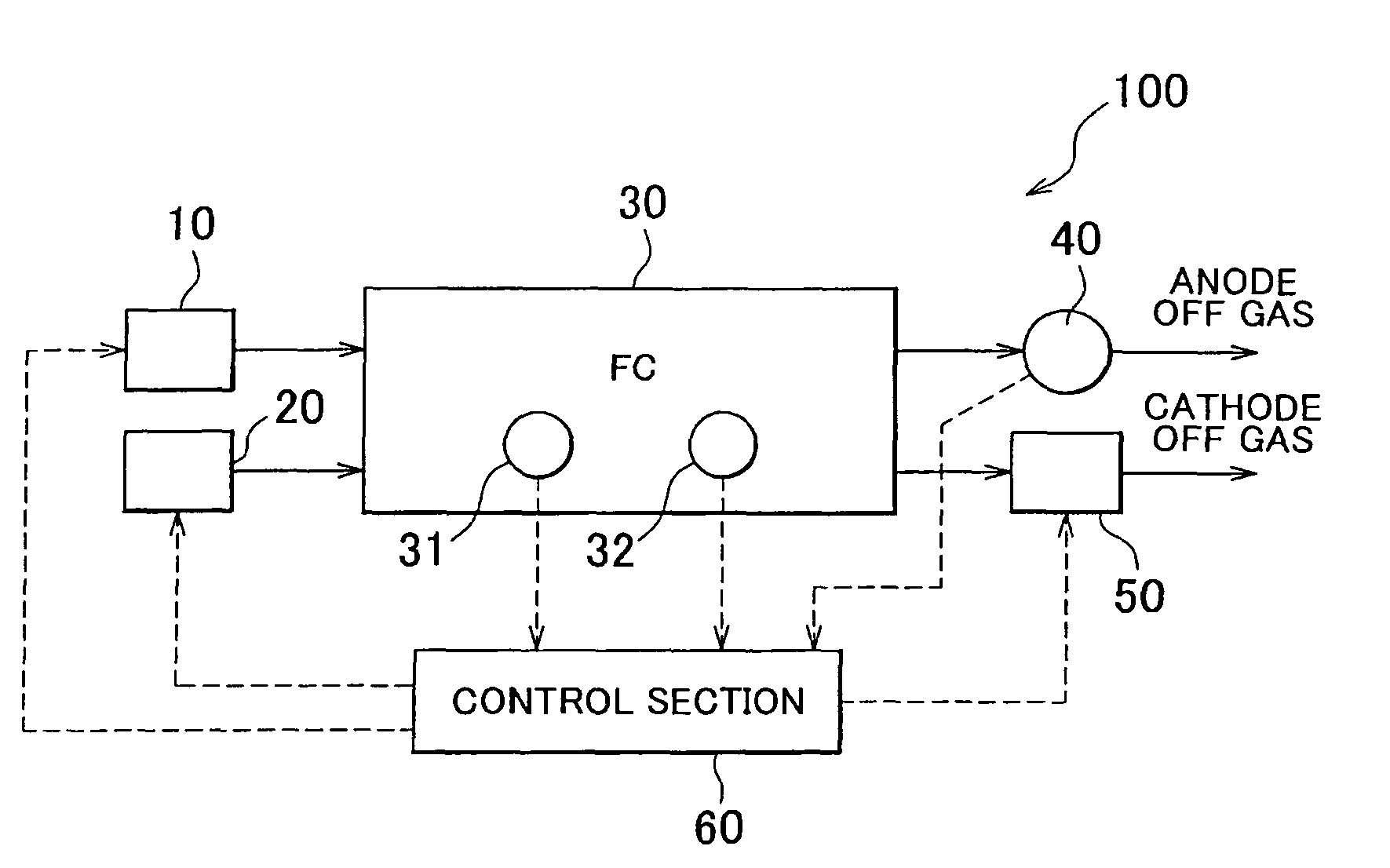
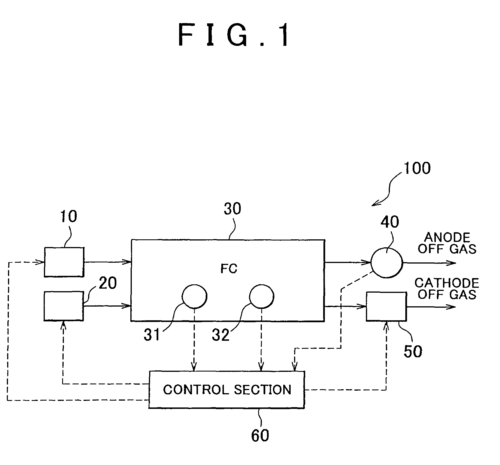
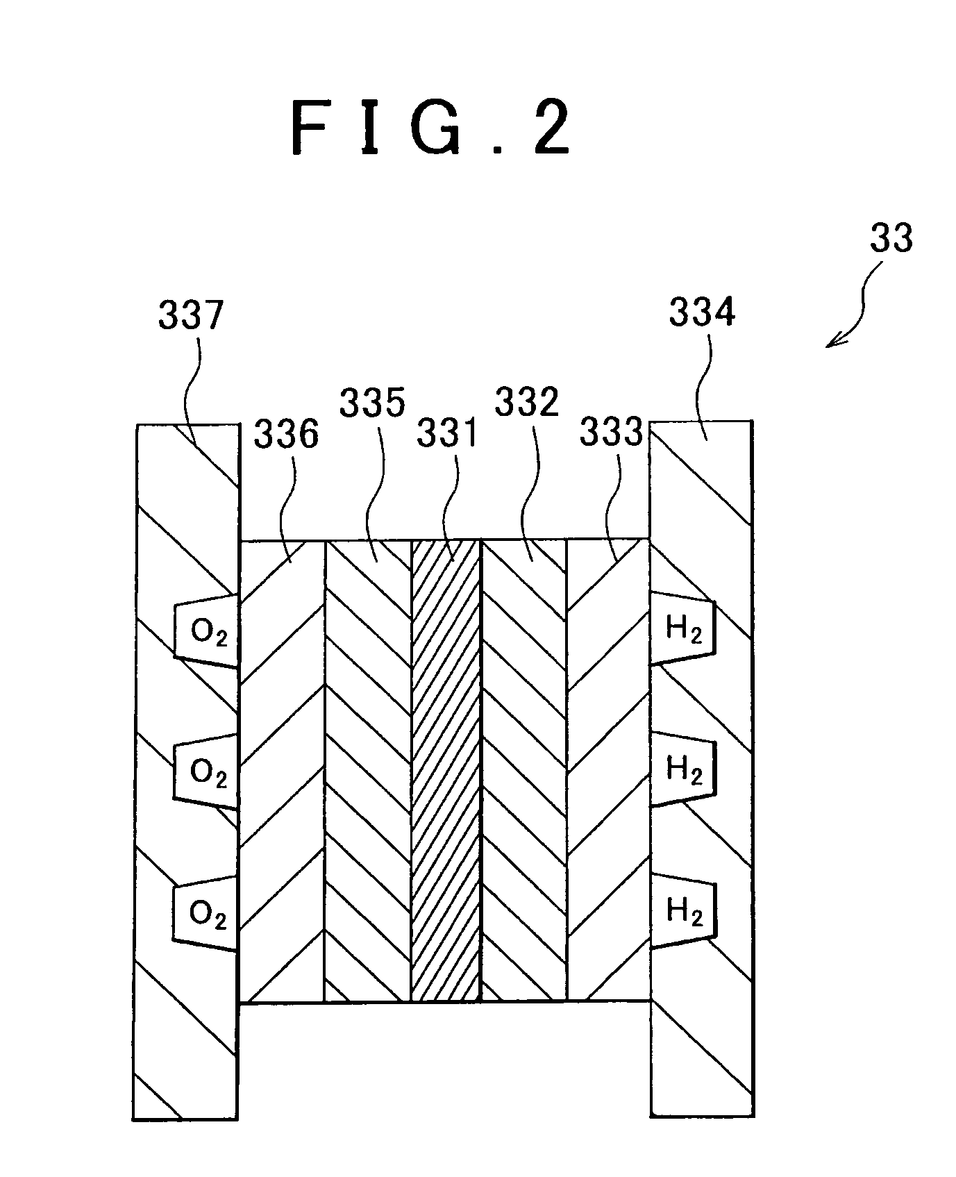
[0029]A fuel cell system 100 in accordance with an embodiment of the present invention is described with reference to FIGS. 1 and 2. FIG. 1 is a schematic diagram showing the overall configuration of the fuel cell system 100. FIG. 2 is a schematic cross sectional view of a cell 33. As shown in FIG. 1, the fuel cell system 100 includes fuel gas supply means 10, oxidant gas supply means 20, a fuel cell 30, a temperature sensor 31, a resistance sensor 32, a dew point sensor 40, a pressure regulation valve 50, and a control section 60.

[0030]The fuel gas supply means 10 supplies fuel gas containing hydrogen to the fuel cell 30. The fuel gas supply means 10 supplies the fuel cell 30 with fuel gas in accordance with instructions from the control section 60. The oxidant gas supply means 20 supplies oxidant gas containing oxygen to the fuel cell 30. The oxidant gas supply means 20 supplies the fuel cell 30 with oxidant gas in accordance with instructions from the control section 60.

[0031]The...


PUM

PropertyMeasurementUnit
temperatureaaaaaaaaaa
thicknessaaaaaaaaaa
current densityaaaaaaaaaa

Abstract

A fuel cell system includes: a polymer electrolyte fuel cell; a resistance sensor that detects the internal resistance of the fuel cell; a dew point sensor that detects the dew point of anode off gas from the fuel cell; and a controller that executes an electrolyte membrane hydration control according to the relationship between the internal resistance and the dew point. According to this configuration, it is possible to define, based on the relationship between the internal resistance and the dew point, the conditions under which the decreased power generation performance of the cell may be quickly recovered.

Description

INCORPORATION BY REFERENCE[0001]This application is based on and claims the benefit of U.S. Provisional Application No. 61 / 064,049, filed Feb. 13, 2008. This application is also based on Japanese Patent Application No. 2007-008776 filed on Jan. 18, 2007. The specification, drawings, and abstract of both of these applications are incorporated herein by reference in their entirety.BACKGROUND OF THE INVENTION[0002]1. Field of the Invention[0003]The present invention relates to a fuel cell system and a fuel cell control method.[0004]2. Description of the Related Art[0005]A fuel cell is a device that generates electric energy using, in general, hydrogen and oxygen as fuel. Because the fuel cell has a minimal effect on the environment and a high energy efficiency, it has been widely developed as a highly desirable energy supply system.[0006]In the fuel cell, an electrolyte layer made of a solid polymer is interposed between an anode and a cathode to form a membrane electrode assembly (MEA...

Claims


Application Information

Patent Timeline
Patent Type & Authority Patents(United States)
IPC IPC(8): H01M8/06H01M8/04
CPCH01M8/04104H01M8/04179H01M8/04231H01M8/0447H01M8/04761H01M8/04805H01M8/0662H01M8/04037H01M8/04141H01M8/04253H01M8/0444H01M2008/1095Y02E60/50
Inventor ARAKI, YASUSHI
Owner TOYOTA JIDOSHA KK
Why Eureka
Try Eureka