Homogeneous charge compression ignition engine operation

a charge compression and ignition technology, applied in the direction of electrical control, process and machine control, instruments, etc., can solve the problems of increasing the temperature of the cylinder, increasing the difficulty of robust and stable control, and increasing the difficulty of cylinder oxygen level, so as to achieve the effect of robust operating set-points

a charge compression and ignition technology, applied in the direction of electrical control, process and machine control, instruments, etc., can solve the problems of increasing the temperature of the cylinder, increasing the difficulty of robust and stable control, and increasing the difficulty of cylinder oxygen level, so as to achieve the effect of robust operating set-points

US20070250256A1Inactive Publication Date: 2007-10-25GM GLOBAL TECH OPERATIONS LLC

Image

  • Homogeneous charge compression ignition engine operation
  • Homogeneous charge compression ignition engine operation
  • Homogeneous charge compression ignition engine operation

Examples


Embodiment Construction

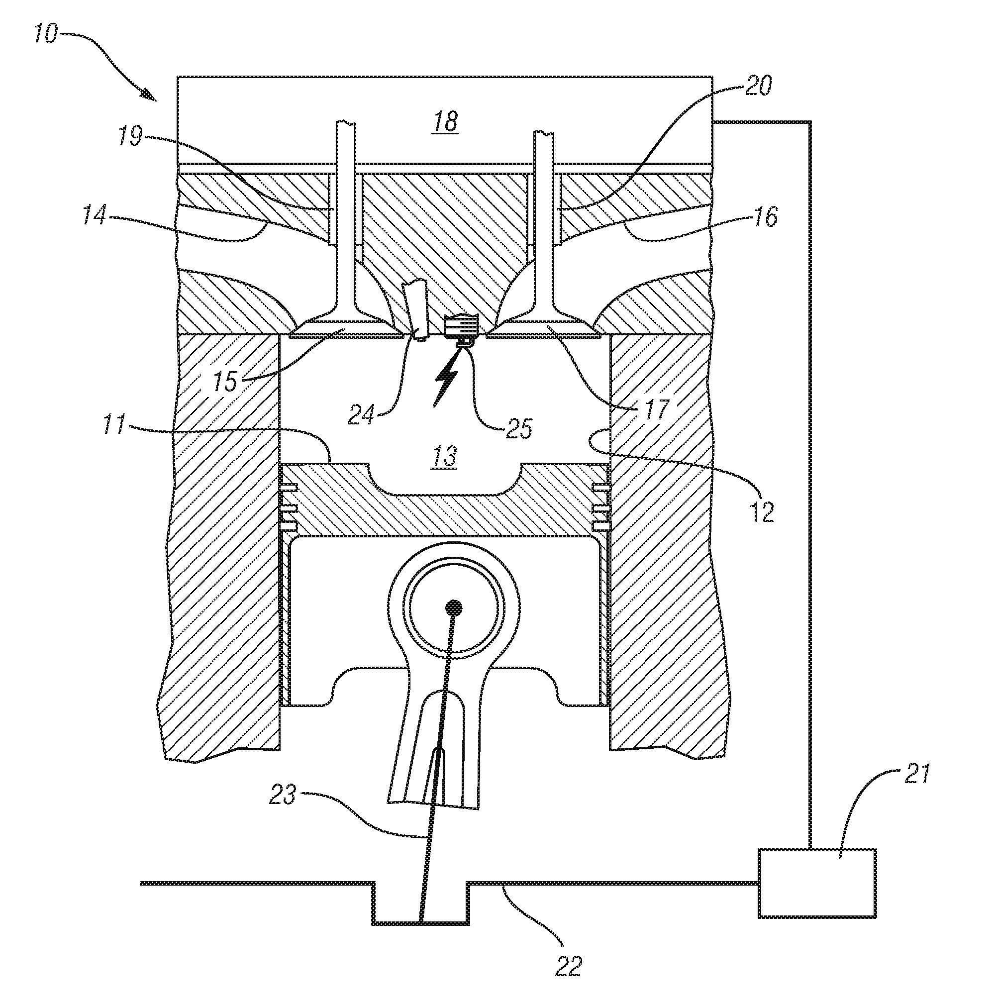
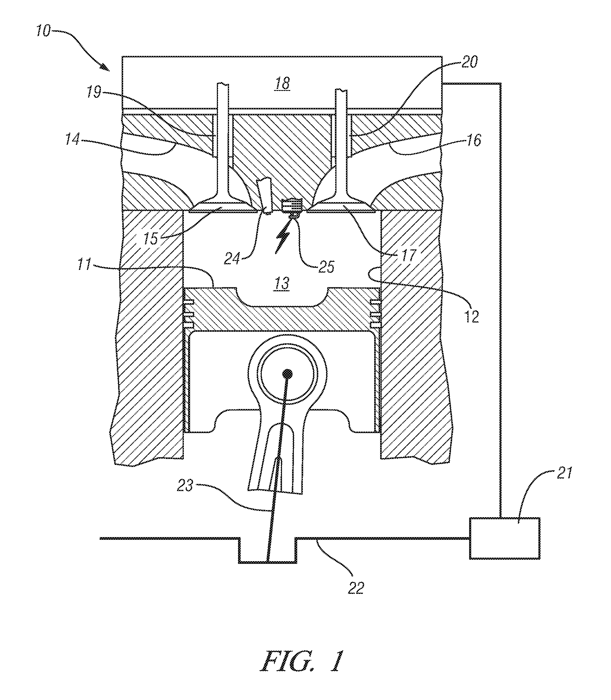
[0019]Referring first to FIG. 1 of the drawings in detail, numeral 10 generally indicates a schematic representation of an exemplary single-cylinder direct-injection four-stroke internal combustion engine. In the figure, a piston 11 is movable in a cylinder 12 and defines with the cylinder 12 a variable volume combustion chamber 13. An intake passage 14 supplies air into the combustion chamber 13. Air flow into the combustion chamber 13 is controlled by an intake valve 15. Combusted gases can flow from the combustion chamber 13 via an exhaust passage 16, controlled by an exhaust valve 17.

[0020]Exemplary engine 10 has a hydraulically controlled valve train with an electronic controller 18, which is programmable and hydraulically controls the opening and closing of both the intake 15 and exhaust 17 valves. The electronic controller 18 will control the movement of the intake valve 15 and exhaust valve 17 having regard to the positions of the intake and exhaust valves 15 and 17 as measu...


PUM


Abstract

An HCCI engine is operated by controlling a plurality of engine operating parameters in accordance with a calibration data set representing equilibrium set-points of engine operation characterized by combustion phasing that is relatively least sensitive to cylinder charge temperature deviations.

Description

CROSS REFERENCE TO RELATED APPLICATIONS[0001]This application claims the benefit of U.S. Provisional Application No. 60 / 794,561 filed on Apr. 24, 2006 which is hereby incorporated herein by reference.TECHNICAL FIELD[0002]This invention relates to homogeneous charge compression ignition (HCCI) engines.BACKGROUND OF THE INVENTION[0003]In homogeneous charge compression ignition (HCCI) engine, combustion is flameless, and spontaneously occurs at the entire cylinder volume. The homogeneously mixed cylinder charge is auto-ignited as the cylinder charge is compressed and its temperature increases. The ignition timing of auto-ignited combustion strongly depends on initial cylinder charge conditions such as temperature, pressure, and composition. Thus, it is important to coordinate the engine inputs, such as fuel mass, injection timing, and valve motion, to ensure robust HCCI combustion. Depending on the valve motion, there are two prevailing operating strategies in an HCCI engine—exhaust re...

Claims


Application Information

Patent Timeline
25 Oct 2007
Publication
US20070250256A1
IPC
G06F19/00; G06G7/70
CPC
F02B1/12; F02B2075/125; F02D41/0057; F02D41/006; F02D41/0065; Y02T10/47; F02D41/3035; F02D2041/001
Inventors
KANG, JUN-MO; CHANG, CHEN-FANG